
Guia de especificações do adaptador de energia
2026-08-27
Cable Material and Durability Specification Guide
2026-09-09
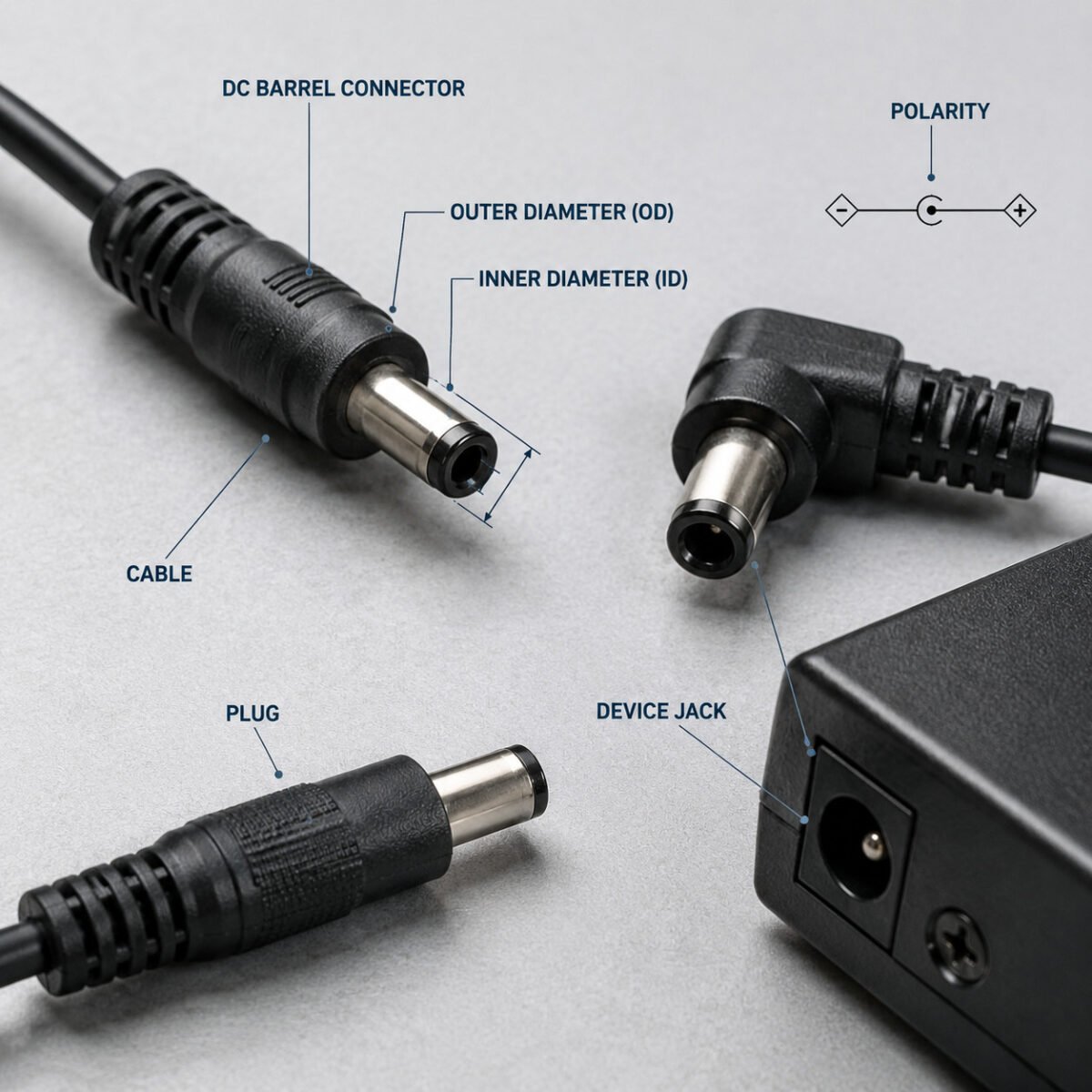
Guia de especificações do conector CC
Guia de especificações do conector CC
Technical reference for selecting the correct DC plug and barrel connector — covering standard sizes, polarity conventions, cable gauge selection, application scenarios, and customization options.

1. DC Connector Key Parameters
Several key parameters determine whether a DC barrel connector is compatible with a target device, including physical dimensions, polarity, electrical requirements, and cable specification. All relevant parameters should be verified together to ensure electrical and mechanical compatibility.
1.1 Connector Size
Barrel DC connectors are commonly specified by the plug outer diameter (OD) and inner diameter (ID), measured in millimeters. The plug dimensions must match the mating device receptacle, including the required contact dimensions and insertion depth. Even when the outer diameter is correct, an incorrect inner diameter or contact length may result in poor contact or an incompatible connection.
The table below lists common barrel connector sizes, their typical current ranges, and common application areas:
| Connector Size (OD × ID) | Designation | Typical Current Range* | Typical Applications |
|---|---|---|---|
| 3.5 × 1.35 mm | DC35135 | Up to 2 A | Selected portable electronics, compact equipment |
| 4.0 × 1.7 mm | DC4017 | Up to 3 A | Selected compact electronics and LED equipment |
| 5.5 × 2.1 mm | DC5521 | Up to 5 A | Routers, CCTV cameras, LED lighting, consumer electronics |
| 5.5 × 2.5 mm | DC5525 | Up to 6 A | Selected industrial and consumer equipment |
| 5.5 × 3.0 mm | DC5530 | Up to 7 A | Selected higher-current equipment and power applications |
| * Current ratings are application- and model-dependent. Actual ratings depend on the connector construction, contact design, cable specification, operating temperature, and other electrical and mechanical conditions. Always confirm the rating against the specific connector and cable assembly specification. | |||
O 5.5 × 2.1 mm connector is widely used across consumer electronics and is available for a wide range of AC-to-DC adapter applications. However, connector dimensions, polarity, voltage, and current ratings must be verified before selecting a replacement adapter. It should not be assumed interchangeable with 5.5 × 2.5 mm — although both share a 5.5 mm outer shell, the 0.4 mm ID difference prevents reliable pin contact and can cause intermittent power delivery.
Verification note: Physical dimensions should be confirmed against the device receptacle specification before specifying a replacement connector. If the connector size is not clearly documented, verify the plug and receptacle dimensions directly rather than relying on the adapter housing alone.
1.2 Polarity
DC barrel connectors carry two conductors: the center pin (inner contact) and the outer sleeve (outer contact). Polarity defines which conductor carries positive voltage and which carries ground. Reversed polarity can damage device circuitry, so matching the polarity marking on the device is essential.

- Center Positive (+): Center pin carries positive voltage; outer sleeve is ground. Commonly used in many routers, CCTV cameras, LED equipment, and other consumer electronics. Identified by a symbol showing + inside the circle, − outside.
- Center Negative (−): Center pin carries ground; outer sleeve carries positive voltage. Found in selected older audio equipment and certain legacy devices. Less common in current production but still specified for niche applications.
Polarity is marked on the device body or adapter label using a circular symbol: a plus or minus sign inside the circle indicates center pin polarity, and the opposite sign outside indicates sleeve polarity. If polarity cannot be confirmed from reliable documentation or markings, it should be verified using an appropriate multimeter and safe measurement procedure.
1.3 Cable Type
The cable connecting the DC plug to the power adapter must carry the required current without excessive voltage drop or heat generation. Wire gauge — specified in AWG (American Wire Gauge) — indicates conductor size. Lower AWG numbers indicate thicker conductors.
| AWG Gauge | Approx. Conductor Diameter | Typical Use |
|---|---|---|
| 24 AWG | 0.51 mm | Lower-current applications and compact cable assemblies |
| 22 AWG | 0.64 mm | General-purpose DC power applications |
| 20 AWG | 0.81 mm | Higher-current applications and longer cable runs |
| 18 AWG | 1.02 mm | Higher-current applications where lower voltage drop is required |
AWG indicates conductor size, but it does not define a universal current rating. The allowable current depends on conductor material, insulation, ambient temperature, cable construction, length, voltage-drop requirements, and the specific connector assembly. Final wire selection should therefore be based on the required current and allowable voltage drop for the complete cable assembly.
Cable jacket material also affects performance in specific environments. PVC (polyvinyl chloride) jackets are suitable for standard indoor applications. For installations requiring greater flexibility, temperature tolerance, or abrasion resistance, alternative jacket materials such as TPE (thermoplastic elastomer) or XLPE (cross-linked polyethylene) are available on selected models. Shielded cable constructions can help reduce electromagnetic interference (EMI) and radio-frequency interference (RFI) in electrically noisy environments. Shielding may be considered when the cable is installed near switching power supplies, motors, RF sources, or other potential interference sources.
2. Applications
DC connector specifications vary by end-use environment. The following categories describe common deployment scenarios and the connector parameters each requires.
2.1 Consumer Electronics
Consumer devices — including home routers, LED lighting strips, portable speakers, and small audio recorders — commonly use barrel connectors such as 5.5 × 2.1 mm with center-positive polarity, although actual connector dimensions vary by device and manufacturer. Current requirements vary by device and application, with cable gauge selected according to the required current, cable length, and allowable voltage drop.
For compact, low-power devices such as portable recorders and selected mini drones, smaller barrel connectors such as 3.5 × 1.35 mm may be used where space constraints are important, subject to the device’s electrical requirements.
2.2 Industrial Equipment
Industrial environments introduce additional demands: higher current, longer cable runs, and exposure to temperature variation or vibration. CCTV systems, LED display panels, and industrial controllers may require larger connector dimensions such as 5.5 × 2.5 mm ou 5.5 × 3.0 mm, with heavier-gauge conductors selected according to the specific device specification.
For industrial deployments, larger conductor sizes are typically preferred to minimize voltage drop over extended cable runs. Shielded cable constructions may be considered where electromagnetic interference from nearby equipment could affect electrical performance or sensitive equipment.
- CCTV and surveillance equipment: Commonly available with barrel connectors such as 5.5 × 2.1 mm, with polarity and cable gauge selected according to the device specification.
- LED display and lighting equipment: May require larger connector dimensions and heavier-gauge conductors for higher-current applications.
- Industrial control equipment: May use locking, threaded, or right-angle connector designs where secure retention and installation space are important.
2.3 Replacement Adapter
When a power adapter requires replacement, the DC connector must match the original device in multiple dimensions: physical size (OD and ID), contact length, polarity, and cable gauge sufficient for the device current draw. A connector that matches the OD but not the ID, or matches the dimensions but not the polarity, will not function correctly and may cause damage.
The following steps support accurate replacement specification:
- Check the Original Specification — Review the original adapter label, product manual, or device datasheet for output voltage, current, polarity, and connector dimensions.
- Verify Connector Dimensions — Confirm the plug outer diameter, inner diameter, and required insertion length against the device receptacle. If the dimensions are uncertain, provide a sample plug or device jack for verification.
- Verify Polarity — Check the polarity symbol on the device or original adapter. If no reliable marking is available, polarity should be verified with appropriate electrical test equipment.
- Select Cable Gauge — Determine the required current and cable length, then select the conductor size based on allowable voltage drop and the ratings of the complete cable assembly.
3. Customization
Beyond standard connector configurations, custom specifications are available to meet device-specific requirements that off-the-shelf connectors do not address.
3.1 Custom Connector
Custom barrel connector designs can be developed for devices with proprietary or specialized power inputs, including non-standard OD/ID combinations and customized pin lengths. Connector plating options include gold-plated contacts for applications requiring enhanced corrosion resistance and stable long-term contact performance, and nickel-plated contacts for general-purpose applications where corrosion resistance and mechanical durability are required.
Right-angle connector bodies are available for installations where a straight plug protrudes too far from the device panel, such as wall-mounted equipment or compact enclosures. Threaded or locking barrel designs provide secure retention in high-vibration environments typical of industrial and transportation applications.
- Dimension Customization — Custom OD and ID dimensions from approximately 2.5 mm to 6.5 mm can be developed for selected applications, subject to connector design and tooling requirements. Pin length and required insertion depth can be specified according to the mating receptacle and connector design tolerances.
- Contact Plating — Gold-plated contacts for applications requiring enhanced corrosion resistance and stable long-term contact performance. Nickel-plated contacts for general-purpose applications where corrosion resistance and mechanical durability are required.
- Body Orientation — Straight, right-angle, and threaded-locking body types. Suitable for space-constrained enclosures and high-vibration industrial settings.
3.2 Cable Length
DC adapter cable lengths commonly range from 1 m to 2 m. For installations requiring extended reach — such as ceiling-mounted devices, rack-mounted equipment, or equipment positioned at distance from the power source — custom cable lengths up to 5.0 m are available for selected applications, with conductor size determined according to current, voltage, length, and allowable voltage drop.
Cable length affects voltage drop, especially in low-voltage, higher-current applications. Longer cables generally require a larger conductor size to maintain the required voltage at the device. As a general selection principle:
- Short cable + low current: smaller conductors may be suitable.
- Longer cable + higher current: larger conductors are typically preferred.
- Low-voltage applications: voltage-drop requirements should be checked carefully.
- Higher-current applications: both conductor size and connector current rating should be verified.
For custom cable assemblies, the recommended AWG should be determined from the required voltage, current, cable length, allowable voltage drop, operating temperature, and connector specification rather than from cable length alone.
When selecting cable length, avoid unnecessary excess cable where possible. Longer cables increase conductor resistance and voltage drop, particularly in low-voltage, higher-current applications. Cable routing and installation should also allow adequate heat dissipation for the intended operating conditions.
3.3 Assembly
DC connector assembly encompasses the processes that join the barrel plug to the cable and the cable to the adapter housing. The quality of these assembly processes affects electrical reliability, mechanical durability, and long-term product performance.
- Overmolding — The cable-to-plug junction is covered and reinforced with an injection-molded thermoplastic overmold that provides strain relief and helps protect the connection from mechanical stress and environmental exposure. Overmold hardness can be specified to balance flexibility and durability for the target application.
- Strain Relief — Strain-relief features at the cable-to-plug junction help reduce mechanical stress on the cable and electrical termination during bending and pulling. Depending on the connector design, strain relief may be provided by molded structures, flexible boots, internal supports, or spring-type components.
- Termination — Cable-to-contact termination methods may include soldering, crimping, or other joining technologies depending on the connector design, conductor construction, electrical requirements, and production volume. The termination method is selected to provide the required electrical continuity, mechanical retention, and production consistency for the specified application.
- Quality Verification — Finished cable assemblies can be tested according to the applicable product specification and customer requirements. Typical checks may include continuity, polarity, contact resistance, insulation resistance, and mechanical pull testing. Dielectric withstand (hipot) testing can be applied where required by the applicable safety standard or product specification.
Need a Custom DC Connector Solution?
Whether you need standard bulk DC cables or fully customized barrel connector assemblies, our team can help you specify the right solution for your application. From custom OD/ID dimensions to specialized cable lengths and overmolding, we support OEM/ODM projects with competitive pricing and flexible MOQ.