

Custom USB Cable and Charger Specification Guide
Custom USB Cable and Charger Specification Guide
Custom USB cable and charger OEM projects require a structured specification process to translate application requirements into production-ready products. For procurement teams and brand managers preparing to source custom USB products, understanding what information to provide — and how that information flows through engineering, prototyping and production — can help reduce project lead times and revision cycles. This guide outlines the requirement information, product specification parameters and OEM process stages needed to define and execute a custom USB cable or charger project.
1. Customer Requirement Information
Defining a custom USB cable or charger project begins with a clear statement of the target product and its intended use. Three categories of information form the foundation for engineering review and quotation.
1.1 Product Family
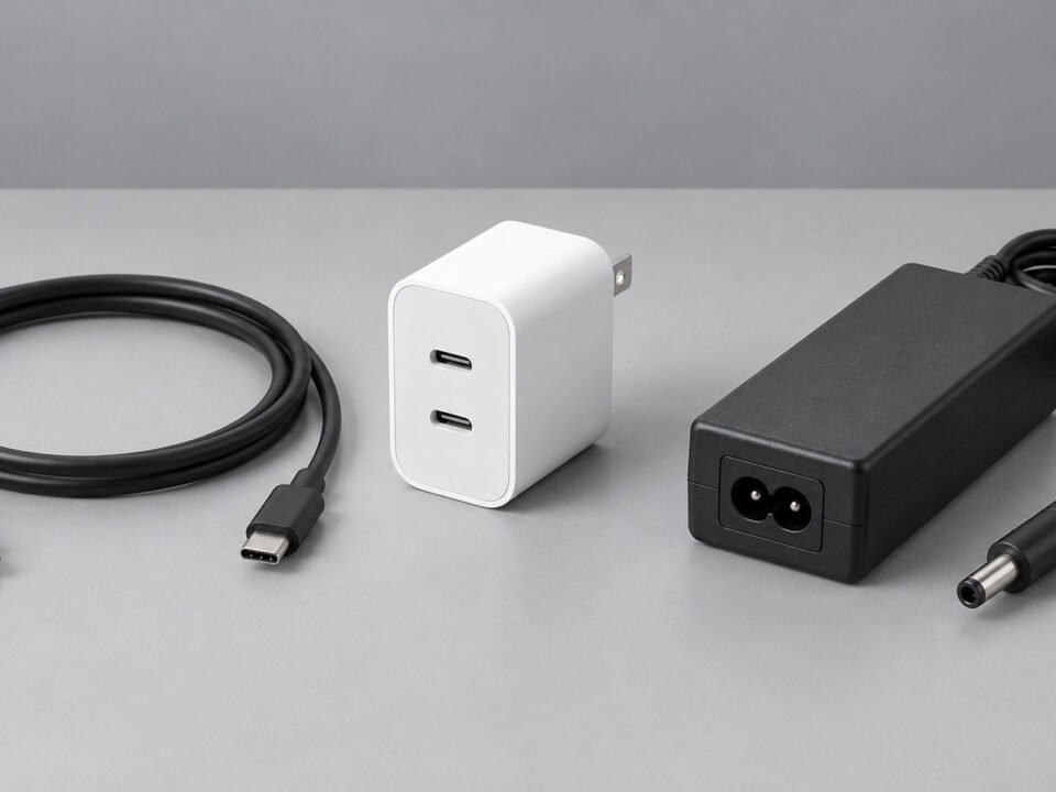
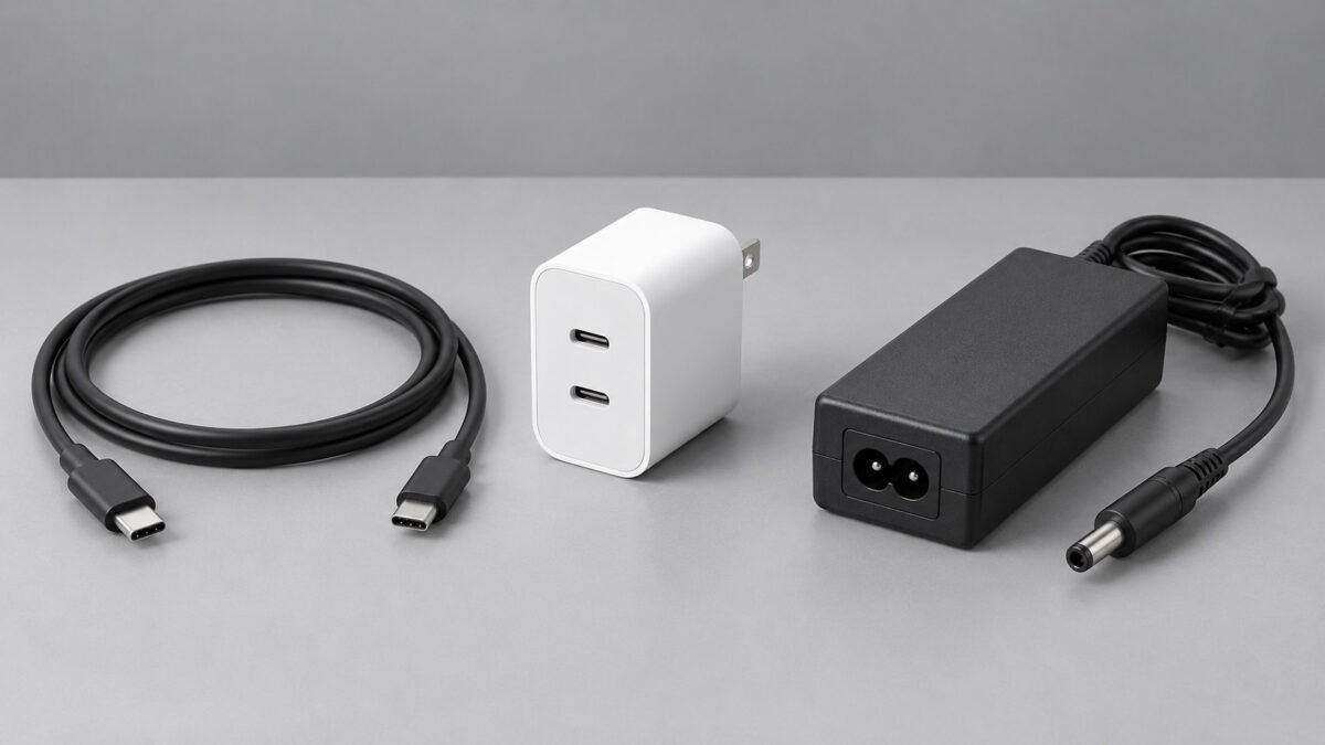
The product family identifies the basic form and intended function of the custom product. Common families include USB cable assemblies, USB chargers, fixed-output power adapters and custom cable assemblies. Connector combination, data capability, power rating, form factor and construction technology should be specified separately.
Common Product Families:
- USB cable assemblies: USB-C to USB-C, USB-A to USB-C, USB-A to Micro-USB and other connector combinations
- USB chargers: wall, desktop and multi-port configurations
- Fixed-output power adapters: barrel connector, terminal or custom DC output
- Custom cable assemblies: USB-to-custom and non-USB connector designs
- Technologies such as GaN may be selected for suitable charger platforms but should not be treated as a separate product form factor.
1.2 Application
The application defines the operating environment and target device. This determines whether the product needs consumer-grade flexibility, industrial durability, waterproof sealing, or specific regulatory certifications for the destination market.
Application Categories:
- Consumer Electronics: smartphones, tablets, laptops, accessories
- Industrial Equipment: factory automation, control systems, instrumentation
- Automotive: in-vehicle charging and infotainment projects, subject to project-specific electrical, environmental, EMC, flammability and qualification requirements
- Medical and Healthcare Equipment: Projects for medical or healthcare equipment require separate review of the applicable electrical safety, EMC, risk-management, traceability and supplier-quality requirements. Standard consumer USB products should not be presented as medical-grade or suitable for patient-connected equipment without project-specific qualification.
- Commercial: public charging stations, retail display units
1.3 Performance Requirements
Performance requirements define the electrical and mechanical parameters the product must meet. For USB cables, this includes data rate, power handling and signal integrity for the cable length. For chargers, this includes output power, port configuration and efficiency targets.
Key Performance Parameters:
- Data capability: USB 2.0 up to 480 Mbps or selected USB 5Gbps, USB 10Gbps, USB 20Gbps, USB 40Gbps and USB 80Gbps designs, subject to model availability and validation
- Video or alternate-mode support: specified separately where required
- Cable construction: passive or active design selected according to the target data rate and cable length
- Power capability: USB PD Standard Power Range supports system power levels up to 100W, while Extended Power Range supports system power levels up to 240W with a compatible source, sink and EPR-rated electronically marked 5A cable. Available cable and charger ratings depend on the selected product platform.
- Cable current capability: compliant USB-C cables may support up to 3A without a 5A cable rating. Operation above 3A requires an electronically marked 5A cable, while EPR operation requires an appropriate EPR-rated cable.
- Charger output: rated power and PDO profiles depend on the selected model. USB PD EPR permits system power levels up to 240W, but the available product portfolio may have a lower maximum rating.
- Signal integrity: applicable electrical, signal-integrity and interoperability testing selected according to the target USB specification, data rate, cable length and passive or active construction

2. Product Specification Definition
Once the requirement information is established, the product specification translates it into defined engineering parameters. Seven specification areas define the physical and electrical identity of the custom product.
2.1 Dimensions and Length
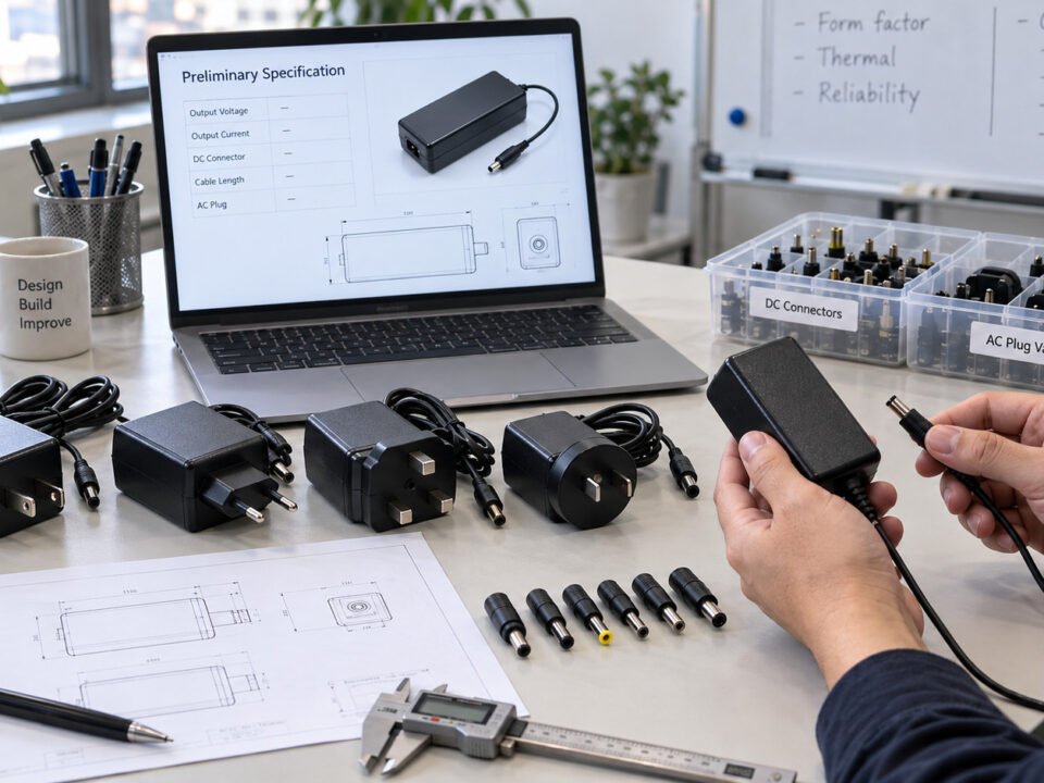
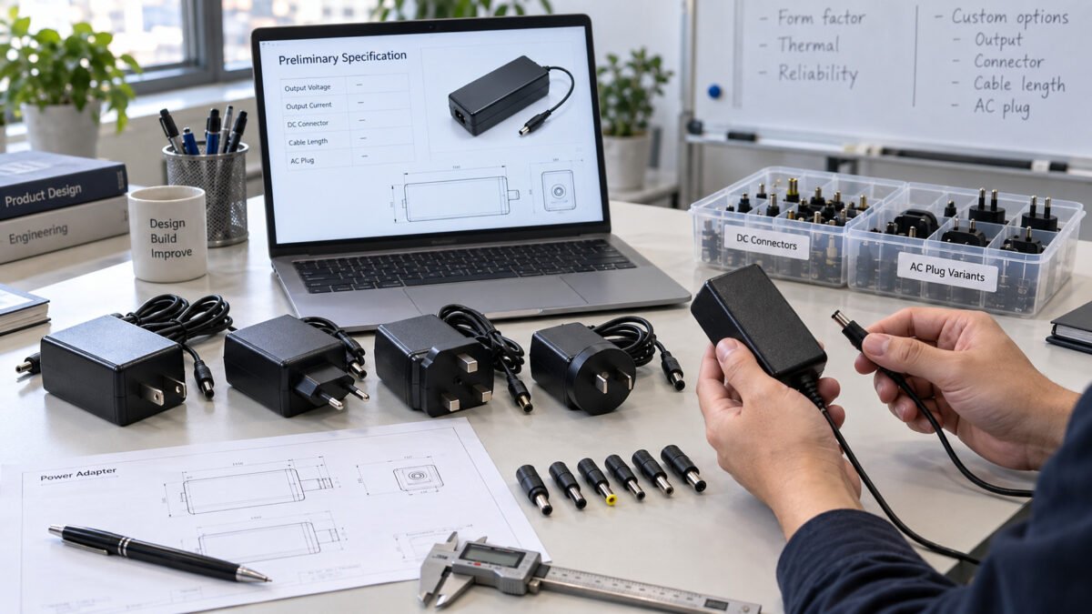
For cable assemblies, dimensions include cable outer diameter, conductor gauge, connector housing dimensions and overall cable length. For chargers, dimensions include housing dimensions, weight, plug type and whether a foldable plug is required.
Size and Length Specification Items:
- Cable outer diameter: defined by the conductor set, shielding, insulation, jacket construction and mechanical requirements
- Conductor gauge: specified separately for power and signal conductors; selection depends on current, voltage drop, data rate and cable length
- Cable length: selected according to voltage-drop and signal-integrity requirements. Passive high-speed cable length is limited by the target data rate and construction; longer reach may require an active design and compatible equipment
- Charger dimensions and weight: confirmed from the selected product platform or approved custom mechanical drawing
- AC plug configuration: selected according to the destination market and applicable plug standard
2.2 Connector
The connector defines the physical interface between the product and the target device. For USB cables, connector options include USB-C, USB-A, Micro-USB, Mini-USB and custom connectors. Connector plating and contact material affect durability and contact resistance.
Connector Specification Items:
- USB-C: a reversible connector interface that can be configured for charging, data and selected alternate modes. Actual USB PD, data-rate and video capabilities depend on the cable wiring, electronic components and connected devices and must be confirmed for each model.
- USB-A: a rectangular interface commonly used on hosts and chargers. Data and charging capabilities depend on the selected USB version and product design.
- Micro-USB: a compact legacy interface still used in selected accessories, industrial equipment and embedded products.
- DC barrel connector: available in selected dimensions and polarity configurations according to the target equipment.
- Contact plating: material, plating thickness and underplating should be specified according to contact-resistance, corrosion and mating-cycle requirements and verified against the connector drawing and agreed test plan.
2.3 Data and Signal Construction
For cable assemblies, data capability must be defined separately from the connector type. The specification should confirm the target USB data rate, video or alternate-mode requirements where applicable, cable length, passive or active construction, shielding and validation method. USB-C connector appearance alone does not confirm data or video support.
Data and Signal Specification Items:
- Target USB data capability
- Video or alternate-mode support where required
- Passive or active cable construction
- Shielding construction, including foil, braid and drain wire where applicable
- Signal-integrity and interoperability validation for the specified cable length
2.4 Material and Mechanical Construction
Cable construction may use PVC, TPE or silicone as the primary jacket material, with nylon or polyester braid added as an optional outer layer. Temperature, flexibility, chemical-resistance and flame-performance claims must be based on the selected compound and completed cable assembly rather than the generic material name.
Cable Material Specification Items:
- Cable jacket: select a specific PVC, TPE or silicone compound according to the required flexibility, abrasion resistance, chemical exposure and operating environment
- Optional braided layer: nylon or polyester braid may be added to improve appearance and surface abrasion resistance
- Rated temperature range: confirmed from the selected material grade and finished-assembly validation
- Conductor material: bare copper or tinned copper selected according to electrical and environmental requirements
Charger Housing Material:
- Charger housing: PC or PC/ABS resin selected for the applicable safety design. Any UL 94 classification, such as V-0, must refer to the specific material grade and tested thickness; it does not by itself certify the finished charger.
- Connector overmold: PVC, TPE or silicone depending on flexibility requirement
- Connector shell or external housing: material and finish selected according to the connector design, corrosion exposure, mechanical requirements and product appearance
2.5 Power
For chargers and power adapters, the power specification defines the output profile. USB PD chargers support negotiated voltage and current per the applicable PDO. Fixed-output adapters maintain a single voltage and current level as stated on the product label.
Power Specification Items:
- USB PD charger: PDO configuration (5V, 9V, 15V, 20V in SPR; 28V, 36V, 48V in EPR), maximum output power per model, port number and power allocation strategy
- Fixed-output adapter: rated output voltage and current (e.g., 12V/2A, 19V/3.42A), connector size and polarity
- Input rating: many international-market models use a rated input range of 100–240 V AC, 50/60 Hz. The actual range must be confirmed from the selected model's label, datasheet and applicable test report.
- Energy efficiency: determine the applicable active-mode efficiency, no-load power and reporting requirements according to the product category and destination market, including U.S. DOE external power supply requirements and EU ecodesign requirements where applicable.
- Battery charging: support for USB BC 1.2, Quick Charge or other model-specific charging protocols where applicable
2.6 Environment and Compliance
The operating environment affects material, sealing, strain relief, shielding and validation requirements. The specification should identify whether the product will be used indoors, outdoors, in vehicles, in industrial equipment or under repeated flexing, abrasion, moisture or chemical exposure.
Environment and Compliance Specification Items:
- Operating and storage temperature requirements
- Indoor or outdoor use
- Flexing, abrasion and pull-force requirements
- Moisture, dust or chemical exposure
- Destination market and applicable regulatory requirements
- Required test reports, declarations or product markings
- Any waterproof or IP claim must refer to the tested complete assembly and the specified mated or unmated condition. A waterproof jacket material alone does not establish an IP rating for the complete product.
2.7 Appearance and Packaging
Appearance defines the visual identity of the custom product. This includes housing color, surface finish, branding method and packaging. For OEM projects, the appearance specification supports consistent brand presentation across the product line.
Appearance Specification Items:
- Housing color: Pantone or RAL color reference for custom color matching
- Surface finish: matte, glossy or textured (e.g., fine sandblast texture)
- Branding: silk-screen printing, pad printing, laser engraving or embossed logo
- Logo size and position: defined on a 2D drawing with dimensions
- Packaging: poly bag, blister pack, custom retail box or bulk packaging
3. OEM Process
The OEM process translates the agreed specification into a production-ready product through four defined stages. Each stage includes review points and outputs that must be confirmed before proceeding to the next.
3.1 Requirement Review
The requirement review stage collects and verifies the customer specification. The engineering team reviews the product family, application, performance requirements and defined product specifications to confirm technical feasibility, identify applicable standards and estimate tooling and unit cost.
Typical Stage Outputs:
- Technical feasibility assessment
- Identification of applicable USB specifications and destination-market requirements
- Preliminary material and cost assessment
- Project timeline estimate
3.2 Engineering Confirmation
The engineering confirmation stage converts the reviewed specification into engineering documents. Typical engineering outputs may include approved mechanical drawings, cable construction sheets, electrical specifications, PDO configuration records and test plans. Availability of detailed schematics, firmware information and BOM data depends on the project scope and confidentiality arrangements.
Typical Stage Outputs:
- Approved mechanical drawings and electrical specifications, as applicable
- Cable construction sheet (for cable assemblies: conductor, shield, jacket, OD)
- PDO configuration record for applicable USB PD charger projects
- Test plan (electrical, mechanical, environmental)
- Updated material and cost assessment
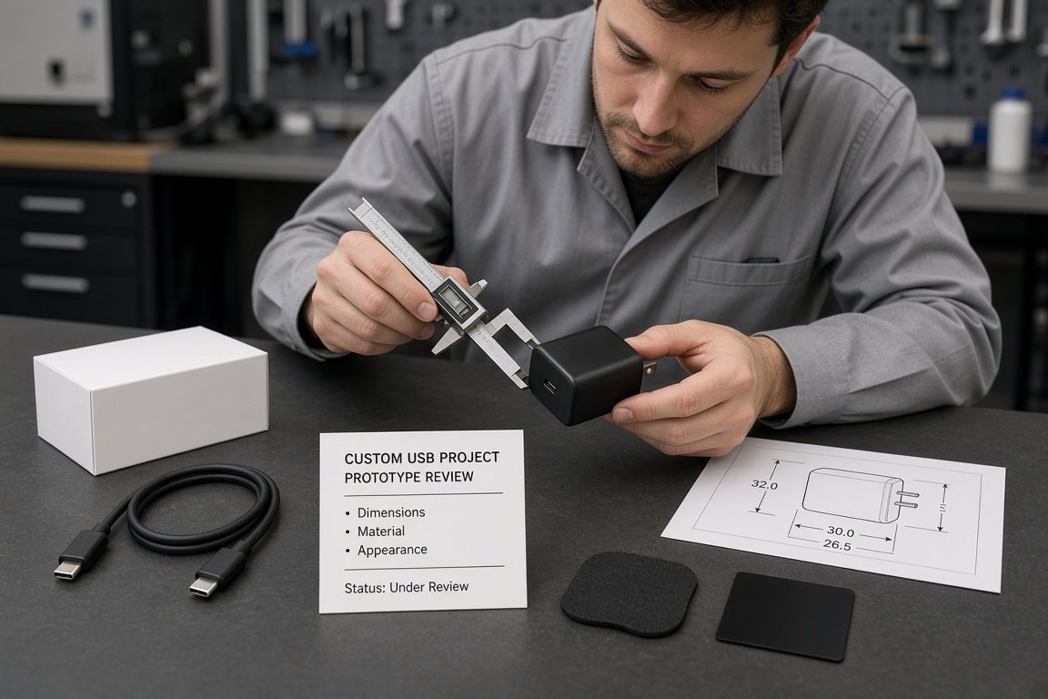
3.3 Prototype
The prototype stage produces initial samples for customer evaluation. Prototypes are built using production-intent materials and processes where feasible. Prototype testing evaluates electrical performance, mechanical fit and appearance and may support pre-compliance assessment. Formal regulatory compliance must be based on the final applicable configuration and the required conformity-assessment or laboratory process.
Functional prototype quantity is defined according to the project scope, tooling status and validation plan.
Typical Stage Outputs:
- Functional prototypes
- Initial test report (electrical performance, dimensional inspection)
- Appearance approval sample (color, logo, finish)
- Customer feedback and revision notes
3.4 Production
Production begins after prototype and specification approval. Tooling, incoming inspection, process controls and production test stations are prepared according to the agreed quality plan. Routine electrical and safety checks may be performed on every finished unit where specified, while extended reliability, environmental and immunity tests are normally conducted through defined sampling plans.
Production Control Items:
- Routine production testing: electrical and safety checks performed on every unit where required by the agreed test plan
- Batch and periodic testing: aging, thermal, mechanical and surge tests conducted on selected units according to the inspection plan
- Final inspection: appearance, labeling, packaging and quantity verification
- Traceability: production records maintained according to the agreed project requirements
Request a Custom Product Review
Provide the target product type, connector combination, required power and data capability, cable length or charger configuration, material preference, operating environment, destination market, estimated order quantity and required validation documents.