
Industrial USB and Power Solutions
2026-09-14
Robotics USB Cable Solutions
2026-09-15
Machine Vision USB Solutions
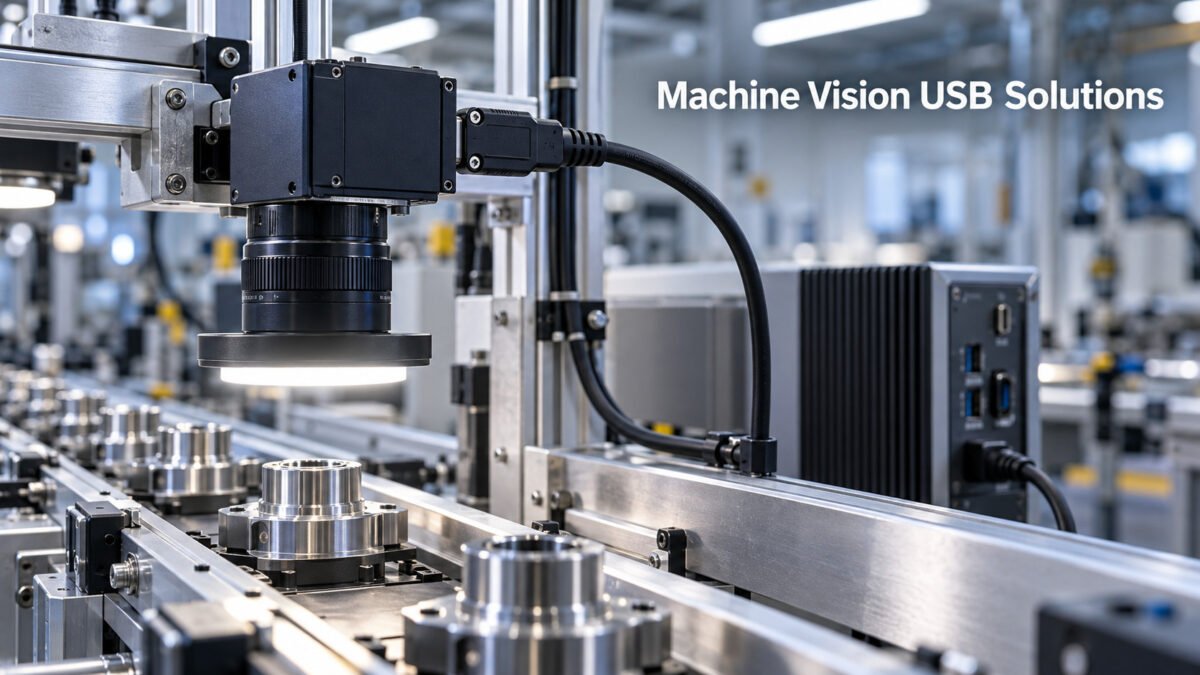
Machine Vision USB Solutions
Industrial machine-vision systems depend on reliable image transfer between cameras and controllers. The selected USB cable can affect available bandwidth, connection stability, installation reliability, and maintenance requirements. Our machine vision USB cable solutions are developed for industrial cameras, inspection equipment, and integrated vision systems. This guide introduces the main cable options and selection factors for industrial cameras, inspection equipment, and integrated vision systems.
1. Machine Vision Requirements
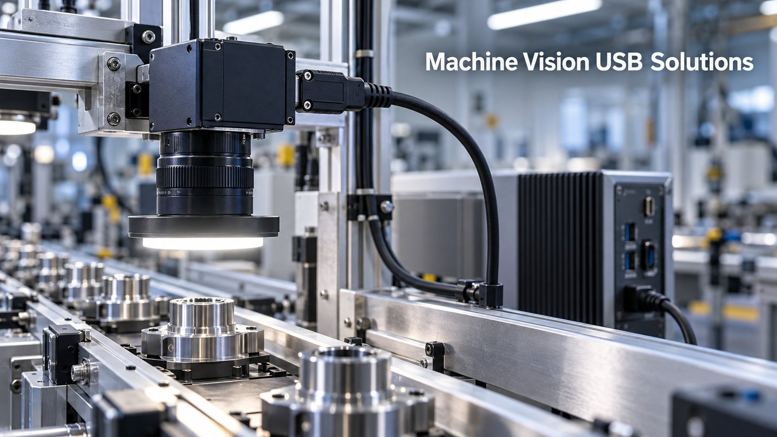
Industrial camera installations place demands on USB cabling that differ from consumer desktop use. Production lines require more consistent connections than typical desktop applications because dropped frames or unexpected reconnection events may interrupt inspection, trigger system faults, or create gaps in quality-control data. Three requirements dominate most installations: high-speed data transfer, stable connection, and long-term operation.
1.1 High-Speed Data
Machine-vision cameras can generate large volumes of image data, especially at high resolutions, high frame rates, or higher pixel depths. The required USB link should therefore be selected according to the camera interface and the actual data throughput of the application. Common options include USB 2.0 at 480 Mbps, and USB 5 Gbit/s or USB 10 Gbit/s for higher-bandwidth cameras; selected USB-C solutions may support higher rates depending on the camera, host, cable construction, and cable length.
The cable must maintain signal integrity at its specified data rate. Excessive attenuation, impedance discontinuities, or electromagnetic interference may cause transfer errors, dropped frames, unstable connections, or failure to establish the intended link speed. For multi-camera systems, available bandwidth at the host controller or hub should also be checked, because multiple cameras may share the same USB bus.
1.2 Stable Connection
A production imaging station runs for entire shifts, and the link between camera and host must remain electrically continuous through vibration, repositioning, and cable strain. Loose or intermittently seated connectors can cause frame loss, communication errors, or unexpected reconnection events. A stable connection depends on correct connector alignment, secure retention of the plug in the receptacle, and suitable shielding against external electromagnetic interference. The connector and cable assembly should also be selected according to the expected mating cycles, vibration, mechanical strain, and handling conditions.
1.3 Long-Term Operation
Machine-vision systems may operate for extended production shifts, so the cable assembly should be selected for the actual electrical, thermal, and mechanical conditions of the installation. For fixed installations, important factors include connector retention, strain relief, conductor size, shielding, jacket material, and the rated operating-temperature range.
Applications involving repeated movement require a cable specifically designed and tested for continuous flexing, drag-chain use, torsion, or robotic motion. A standard industrial cable or locking connector does not by itself make the assembly suitable for continuous movement. Flex-life claims should be stated only for selected models and under defined test conditions.
2. Product Solutions
Several categories of USB cable address machine-vision requirements. These solution categories are not mutually exclusive: a machine-vision cable may combine the required data rate, an industrial jacket, a locking connector, and continuous-flex construction in one customized assembly. The choice depends on where the camera is mounted, the environmental exposure, and how the plant operates.

2.1 High-Data-Rate USB Cable
High-data-rate USB cables are designed to support the specified USB link speed over a defined cable length. Depending on the model, available performance may include USB 2.0 at 480 Mbps, USB 5 Gbit/s, or USB 10 Gbit/s. Connector options may include USB-A, USB-B, USB Micro-B, and USB-C, subject to the interfaces used by the camera and host.
Cable construction may include controlled-impedance signal pairs, foil or braid shielding, and molded strain relief, depending on the required data rate and operating environment. These cables are suitable for fixed camera installations where a standard friction-fit connector provides sufficient retention. Data rate, connector combination, cable length, and qualification test requirements should be confirmed for each project.
2.2 Industrial USB Cable
Industrial USB cables are available for installations exposed to oil, coolant, abrasion, temperature variation, or repeated handling. Depending on the selected model, options may include oil-resistant jackets, reinforced strain relief, enhanced shielding, flame-retardant materials, and specified operating-temperature ranges.
For washdown or dusty environments, a sealed connector system may be required. Any IP rating should apply to a defined connector assembly in its properly mated and installed condition, rather than to an open standard USB plug alone. Environmental resistance, material compatibility, and applicable test requirements should be confirmed according to the customer's equipment and operating conditions.
2.3 Locking USB Cable
Locking USB cables use screw-lock or other compatible retention features to reduce the risk of accidental disconnection caused by vibration, cable pull, or equipment movement. The locking mechanism must match the camera or host receptacle, including the connector type, screw position, thread specification, and available installation space.
Locking versions may be combined with the required data rate, shielding, jacket material, and strain-relief design. For applications involving continuous movement, the locking connector should be paired with a cable specifically rated for the required flexing, torsion, or drag-chain conditions. Connector retention alone does not establish continuous-motion suitability.
3. Selection Factors
Choosing the right cable for a given imaging station means matching cable properties to the required data speed, the routed cable length, and the environment and motion the installation presents. Evaluating all three together before purchase avoids choosing a cable that works on a bench but degrades on the actual line.
3.1 Data Speed
Confirm the USB interface and required link speed of both the camera and the host. The connector shape alone does not determine data performance: for example, USB-C cables can support different data rates depending on their internal construction and specification.
Select a cable that supports the required data rate at the intended length and with the required connector combination. A higher-rated cable may operate with a lower-speed device when the connectors, USB modes, power requirements, and system configuration are compatible, but the final connection will operate at the highest capability shared by the host, device, and cable. For multi-camera systems, also confirm the available bandwidth of the host controller and any intermediate hub.
3.2 Cable Length
Cable length affects signal attenuation and the maximum data rate that can be supported reliably. The permitted passive length depends on the USB speed, cable construction, connector type, and applicable system specification, so one universal maximum length should not be applied to every USB cable.
For longer distances, selected active copper cables, optical USB cables, hubs, or extension systems may be considered. Their supported data rate, maximum specified length, directionality, power requirements, and compatibility with the camera and host must be verified. When calculating length, include bends, service loops, cable-tray routing, and maintenance access, while avoiding unnecessary excess cable.
3.3 Environment and Motion
Confirm whether the cable will remain fixed, move occasionally, or flex continuously during machine operation. Fixed installations generally require suitable shielding, strain relief, and jacket protection. Repeated movement may require a high-flex, drag-chain, torsion-rated, or robotic cable with a defined test method and bend radius.
Oil, coolant, cleaning agents, abrasion, temperature, electromagnetic noise, vibration, and washdown conditions should also be evaluated. Depending on the application, the cable may require an oil-resistant jacket, enhanced shielding, a compatible locking connector, or a sealed connector system with a specified protection rating. Environmental and flex-life claims should always be linked to the selected model and its test conditions.
3.4 Quick Selection Reference
| Selection Item | What to Confirm |
|---|---|
| Connecteur | Camera-side and host-side connector; locking dimensions |
| Data | USB 2.0, USB 5Gbps, USB 10Gbps, or another specified mode |
| Pouvoir | Bus-powered or separate power; required voltage and current |
| Longueur | Routed length, service loop, passive or active solution |
| Motion | Fixed, occasional movement, drag chain, torsion, or robotic use |
| Environnement | Oil, coolant, abrasion, temperature, EMI, dust, or washdown |
| Personnalisation | Jacket, shielding, overmold, labeling, packaging, and testing |
4. Applications
The cable solutions covered above are deployed across the imaging equipment used in manufacturing and quality control. Three application classes capture most of the usage in this space.
4.1 Industrial Camera
The industrial camera is the most direct application of these cables. Area-scan cameras, line-scan cameras, and 3D imaging cameras each output image data that must reach a host or controller intact. Depending on the mounting, a camera uses a high-data-rate cable where the position is fixed, an industrial cable where the enclosure is exposed to the plant environment, or a locking cable where vibration or cable pull could loosen the connection, with a continuous-flex construction added when the cable moves repeatedly during operation. The cable should therefore support the required link speed and image-transfer workload at the selected length. Because cameras are frequently exchanged or upgraded, standardizing compatible connector types, data rates, cable lengths, and locking configurations can simplify spare-parts management and field replacement.
4.2 Inspection Equipment
Inspection equipment such as automated optical inspection stations, inline measurement systems, and assembly-verification machines relies on cameras viewing parts as they pass on a conveyor. These stations often run continuously and sit close to the production flow, so they combine the data-speed demand of the cameras with the environmental exposure of the factory floor. Industrial cable constructions may provide resistance to specified oils or cleaning agents, while compatible locking connectors can reduce the risk of disconnection caused by conveyor vibration. These features may be combined when both environmental protection and connector retention are required. Consistent image delivery helps keep inspection outcomes repeatable from part to part, which supports the confidence a quality-control department places in the system's pass-or-fail decision.
4.3 Vision Systems
In a complete vision system, USB cables commonly connect compatible cameras to a controller or industrial PC. Lighting, triggering, I/O, and other system components may use separate power or communication connections. Depending on the camera's power requirements and the capabilities of the host port, a compatible USB connection may carry both image data and bus power; cameras requiring more power may need a separate power input.
System integrators typically select cable assemblies for the whole line, balancing speed, length, and environment across every camera position so the system behaves predictably. Standardizing on a small set of proven cable assemblies reduces inventory variety and speeds up qualification of the next platform, since cables are field-replaceable without reworking the camera or controller.
5. Custom Machine-Vision USB Cable Solutions
OEM and ODM cable assemblies are available for industrial cameras, inspection equipment, and integrated vision systems. Available options depend on the project specification and may include USB-A, USB-B, USB Micro-B, and USB-C connector combinations; screw-lock designs; customized cable lengths; shielding structures; conductor sizes; molded strain relief; oil-resistant or high-flex jacket materials; and customer-specific labeling and packaging.
Performance and environmental claims are confirmed according to the selected construction and agreed test requirements. Where required, samples can be prepared for electrical, mechanical, and equipment-level compatibility evaluation before mass production.
Request a Cable Recommendation
To recommend a suitable industrial camera cable, the following parameters should be provided:
- Camera and host connector types
- Required USB data rate
- Required cable length
- Camera power requirement
- Fixed, occasional-motion, or continuous-flex installation
- Locking or sealed connector requirements, including any required IP rating
- Operating temperature and exposure to oil, coolant, dust, or washdown
- Estimated order quantity and customization requirements