

How to Select USB Cable for Industrial Applications
How to Select USB Cable for Industrial Applications
USB cables are used in industrial environments for data acquisition, equipment programming, sensor connectivity, machine vision and communication between controllers and host systems. Compared with many consumer installations, industrial USB applications may involve greater mechanical stress, environmental exposure and repeated operating cycles. The selected cable must maintain the required data, power and mechanical performance under the specified operating conditions.
Part 1: Industrial Environment Challenges
Industrial environments can impose mechanical, environmental and operational stresses that general-purpose consumer USB cables may not be designed or validated to withstand. Selecting a cable without considering these conditions can lead to signal degradation, intermittent connections, mechanical failure and unplanned equipment downtime. The following factors should be evaluated when specifying USB cables for industrial use.
Vibration
Industrial equipment such as motors, pumps, compressors and production machinery generates continuous or intermittent vibration. Vibration transmits through equipment frames and mounting structures to connected cables and connectors. Over time, vibration can loosen connector mating, abrade insulation at contact points and fatigue conductor strands at stress concentration areas. Cables in high-vibration environments may require strain relief, secure routing, reinforced overmold designs and connector locking mechanisms to maintain a stable connection.
The vibration profile — frequency, amplitude and direction — varies by equipment type and installation location. Cables located near rotating machinery or pneumatic tools experience different vibration characteristics than those mounted on structural frames. The selected cable and connector system should be evaluated against the vibration profile of the target installation, and the connector retention mechanism should be appropriate for the expected vibration severity.
Movement
Moving equipment such as robotic arms, linear stages, cable carriers and articulated mechanisms subjects USB cables to repeated flexing, bending and torsion. General-purpose USB cables may use stranded conductors but are not necessarily designed or validated for continuous dynamic movement. High-flex cable designs typically use fine-stranded conductors, controlled conductor and shield lay, flexible jacket compounds and purpose-designed strain relief. Flex-life performance must be specified together with the applicable test conditions.
Flex life is typically specified by the number of bending cycles at a defined minimum bend radius. The actual flex life depends on the cable construction, conductor gauge, bend radius, travel speed, acceleration profile and ambient temperature. Cables in cable chains should be selected for the applicable flex-life rating and installed with proper routing, spacing between parallel cables, fixed-point clamping and adherence to the minimum bend radius specified by the cable design.

Dust
Manufacturing facilities, mining sites, woodworking shops and similar environments generate dust and particulate matter that can enter connector interfaces and accumulate on cable surfaces. Dust ingress can cause contact resistance, signal interruption and connector wear over repeated mating cycles. In environments with conductive or corrosive dust, the risk of electrical shorting or contact degradation increases.
Dust protection measures include sealed connector systems, protective caps for unmated connectors, IP-rated assemblies and cable routing that minimizes exposure to dust-generating processes. The level of protection should be matched against the specific dust type, particle size and concentration in the target environment.
Moisture
Moisture from humidity, condensation, washdown procedures or direct liquid exposure can affect USB cable performance and connector reliability. Water ingress into connector interfaces can cause corrosion, short circuits and signal degradation. In food processing, pharmaceutical and outdoor installations, cables may be subjected to regular washdown or exposure to cleaning chemicals.
Moisture protection options include IP-rated cable assemblies, sealed connectors, overmolded cable-to-connector junctions and jacket materials resistant to water absorption and chemical exposure. A waterproof or IP claim must refer to the tested complete assembly and the specified mated or unmated condition. A waterproof jacket material alone does not establish an ingress protection rating for the complete product. The target protection level and chemical resistance should be verified for the selected cable design and intended operating condition.
Frequent Connection
Industrial applications such as test stations, programming interfaces and portable diagnostic equipment require repeated cable connection and disconnection. Connector durability depends on the applicable connector specification and the validated product design. Standard USB-A and USB-B connectors are commonly evaluated to 1,500 insertion and extraction cycles, while USB-C connectors are designed to meet a 10,000-cycle durability requirement under the applicable USB requirements. Mini-USB, Micro-USB, custom and locking connector systems may have different ratings. Actual assembly life can also be affected by contamination, misalignment, side loading and operating conditions, so mating-cycle claims should identify the connector type and test method.
For applications with frequent connection cycles, connectors with higher mating-cycle ratings, robust contact plating and secure retention mechanisms should be considered. Locking connector designs can prevent accidental disconnection while still allowing controlled mating and unmating. The connector system should be chosen based on the expected connection frequency and required mechanical durability.
Part 2: Product Selection
Based on the environmental challenges identified in Part 1, four overlapping cable categories address common industrial requirements: rugged, high-flex, sealed or IP-rated, and locking cable assemblies. An industrial application may require features from several categories, such as a high-flex cable with a sealed locking connector.
Before selecting a product category, confirm the connector combination, required USB data rate, finished cable length, passive or active construction, bus-power or USB Power Delivery requirement, jacket material, shielding design, motion profile, temperature range, chemical exposure and required ingress protection. A rugged, high-flex, sealed or locking construction does not by itself establish USB data-rate, power or IP performance.
Industrial construction does not automatically extend the passive distance supported at a given USB data rate. The required data rate must be validated over the finished cable length. Longer high-speed links may require a compatible active cable or another suitable system architecture, depending on the host, device and USB specification.
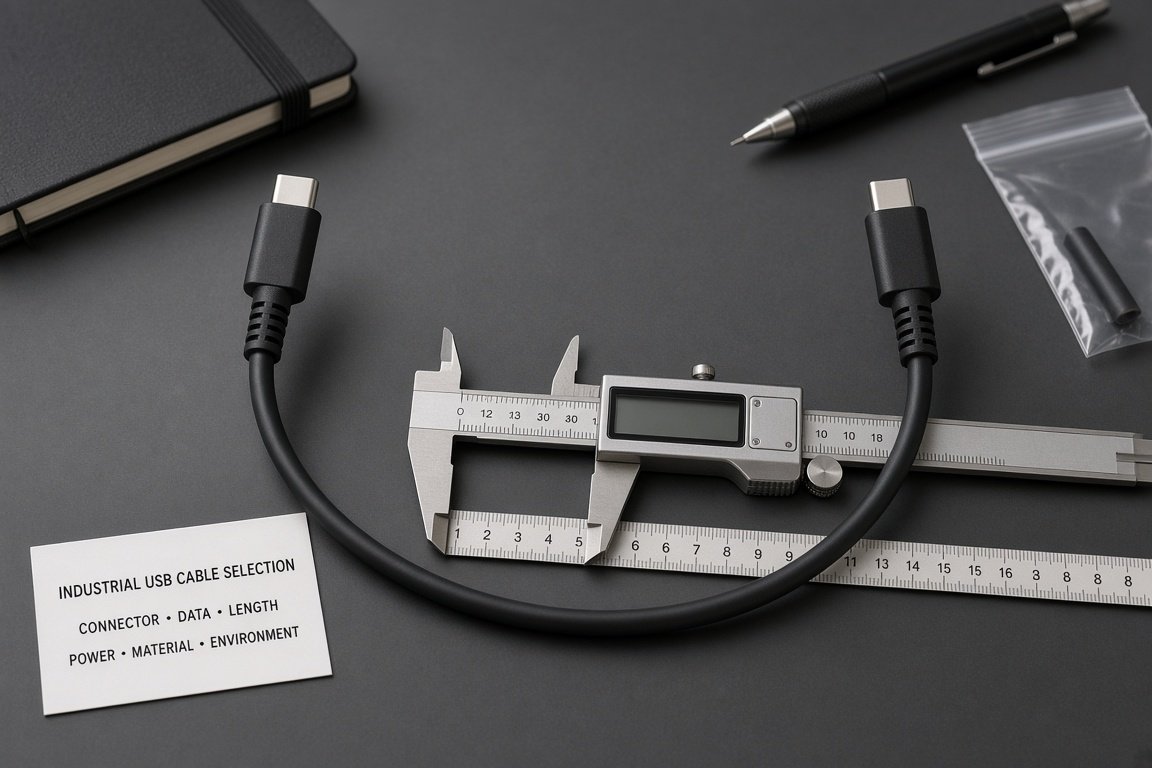
Rugged USB Cable
Rugged USB cables are designed for harsh environments where general-purpose cables would fail prematurely. Construction features may include reinforced overmold designs, thick-walled jacket compounds, braided or foil shielding selected for EMI control, with separate mechanical reinforcement where required, strain relief at connector junctions and impact-resistant connector shells. Jacket materials may include selected PVC, TPE or polyurethane compounds with abrasion, oil and chemical resistance suited to the target environment.
Rugged cables are suited for industrial floors, manufacturing lines, mining sites and other environments with mechanical stress, dust, debris and handling impact. The selected cable should be evaluated against the specific mechanical, chemical and thermal conditions of the installation. Shielding performance should be checked for the EMI environment, and material claims should be based on the completed cable construction rather than the jacket material name alone.
High Flex USB Cable
High flex USB cables are designed for continuous motion applications. They use fine-stranded conductors, controlled conductor and shield lay, flexible jacket compounds and purpose-designed strain relief to endure repeated bending, torsion and flexing. The flex life is specified by the number of bending cycles at a defined minimum bend radius, and the actual performance depends on the cable construction, conductor gauge, travel speed, acceleration profile and ambient temperature.
High flex cables are suited for cable chains, robotic arms, linear guides, articulated mechanisms and other moving equipment where the cable undergoes continuous or frequent motion. Installation in cable carriers requires attention to cable routing, spacing between parallel cables, fixed-point clamping and adherence to the minimum bend radius specified by the cable design. The selected cable should match the motion profile and flex-life requirement of the target application.
Sealed or IP-Rated USB Cable Assembly
Sealed USB cable assemblies may use sealed connectors, overmolded cable-to-connector junctions and water-resistant jacket materials to reduce moisture ingress. An IP rating should be stated only when the complete assembly has been tested under the applicable conditions.
Sealed or IP-rated cable assemblies may be considered for outdoor installations, food processing facilities, pharmaceutical environments and washdown areas, provided that the specified ingress protection, material, chemical-resistance and regulatory requirements match the application.
Locking USB Cable
Locking USB cables use connector designs with mechanical locking mechanisms that secure the mated connection against vibration, pulling and accidental disconnection. Locking options include threaded (screw-lock) connector shells, push-pull locking mechanisms and latch designs integrated into the connector housing.
These mechanisms help maintain full connector engagement and reduce the risk of signal interruption caused by vibration, pulling or accidental disconnection.
Locking cables are suited for fixed installations on production equipment, control panels, test fixtures and permanently mounted devices where connection stability is critical. The locking mechanism should be compatible with the equipment interface and should not interfere with adjacent connectors or enclosure access. For applications requiring periodic disconnection, the locking mechanism should allow controlled mating and unmating without excessive force or tooling where possible.
Part 3: Applications
The following scenarios highlight cable considerations for common industrial applications. Confirm that the cable, host and device support compatible USB data-rate specifications and that the cable construction is validated for the target operating environment.
Automation
Industrial automation systems use USB cables for communication between programmable logic controllers, human-machine interfaces, sensors and host computers. These installations often involve fixed wiring inside control cabinets, connection to field-mounted devices and integration with moving actuators or conveyors. Cable requirements vary by location: cables inside cabinets may need flame-performance-rated jackets, while cables exposed to the production environment may require oil resistance, shielding and mechanical protection.
When USB cables must share a cable carrier or run near motor, servo or variable-frequency-drive wiring, the installation should be evaluated for cable separation, routing, shield construction, shield termination and grounding. Shielding alone does not guarantee reliable data transmission in a high-EMI environment. The selected cable should match the USB data specification of the connected devices and the mechanical and environmental conditions of the installation.
Robotics
Robotic systems subject USB cables to multi-axis movement, including bending, torsion and variable-speed motion along articulated arms and end effectors. Depending on the duty cycle and service-life target, a robotic cable may require validated performance over hundreds of thousands or millions of movement cycles. Flex-life claims should state the test method, bend radius, travel distance, speed, acceleration, torsion condition and temperature. High-flex cable designs with fine-stranded conductors, controlled internal construction and flexible jackets may be selected for these applications.
Cable routing on robots requires attention to the minimum bend radius, the cumulative cable length through multiple joints, and the potential for torsion during rotation. Strain relief at connector junctions and secure clamping along the robot arm help distribute mechanical stress. The selected cable should match the motion profile, flex-life requirement and environmental conditions of the robotic application.
Machine Vision
Machine vision systems use USB cables to transfer image data from cameras to processing units. High-resolution cameras and high-frame-rate inspections require cables that support the target USB data rate — USB 5Gbps, USB 10Gbps or higher — with stable signal integrity over the required distance. Cable shielding helps maintain signal quality in environments with variable-frequency drives, motors and other EMI sources.
Machine vision cameras are often mounted on moving stages or robotic arms, requiring a combination of high-flex durability and validated high-speed data performance. For bus-powered cameras, confirm the host-port power capability, camera current requirement, cable length, power-conductor resistance, connector contact resistance and resulting voltage drop. A cable's data-rate rating does not establish its bus-power or USB Power Delivery capability. The finished cable assembly should be verified for both data and power performance with the target camera and host.
OEM and ODM Customization
Industrial USB cable customization may include connector combinations, cable length, conductor configuration, shielding construction, jacket material, overmold design, strain relief, locking or sealed interfaces, color, labeling and packaging. Available options depend on the target USB data rate, power requirement, environmental conditions, production feasibility and required validation. Custom pinouts or non-standard equipment interfaces are application-specific configurations and should not be represented as standard USB connections unless the applicable USB requirements are met. The pin assignment must be confirmed against the target equipment specification before sampling and production.
Request an Industrial USB Cable Selection Review
Provide the target equipment type, connector combination, required data rate, cable length, power requirement, environmental conditions (vibration, movement, dust, moisture, temperature range), flex-life requirement, target protection level, material preference, destination market and estimated order quantity. These details support specification review, sample planning and OEM/ODM quotation.