

Smart Home and IoT Power Solutions
2026-09-16
Complete Power and Connectivity Solutions
2026-09-17
Custom USB Cable Manufacturing Process
Custom USB Cable Manufacturing Process
A custom cable rarely starts as a drawing. It usually starts as a gap — a connector that does not fit the housing, a length that leaves too much slack, a jacket that fails in the field, or a brand that needs its accessory to look like part of the product rather than an afterthought. Closing that gap in a repeatable, documented way is what separates a one-off sample from a manufacturable part. The process below describes how a requirement is captured, translated into a buildable design, proven through samples, and then held stable through volume production.
1. Why a Custom USB Cable Is Needed
Custom USB cable manufacturing helps OEM buyers and brand owners specify a cable assembly for their product and installation requirements. A standard USB cable is designed for general-purpose use. It suits many everyday applications such as charging a phone, connecting a keyboard, or connecting a peripheral. Yet a considerable number of industrial, commercial, and branded product projects cannot be completed with off-the-shelf products alone. In these cases, a custom cable can help meet the project's fit, performance, and appearance requirements. Custom manufacturing gives a buyer control over the physical and electrical characteristics of a component that is otherwise fixed by standard mass-market designs. For wholesalers and brand owners, a custom cable may reduce assembly work and simplify product integration. Overall cost depends on the design, tooling, order quantity, and testing requirements. The sections below describe the situations in which a custom cable is a suitable choice, followed by the development process used to bring a custom design into production.
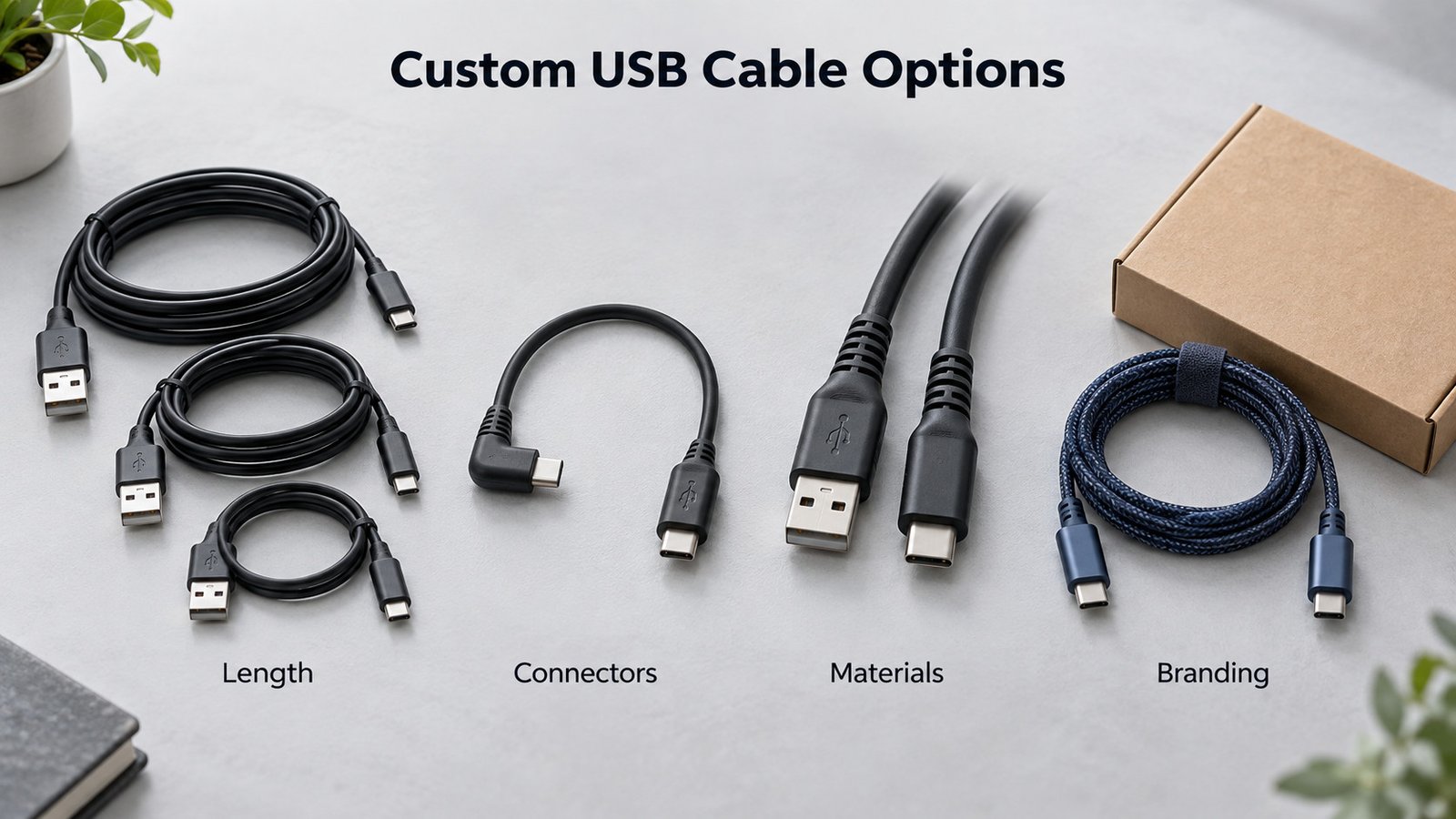
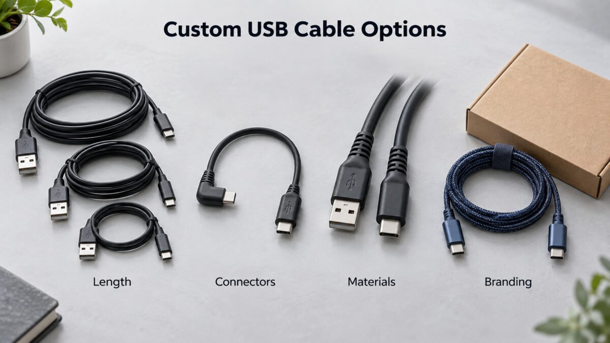
1.1 Special Length
Standard cables are available in common lengths, but equipment installations may require a different length to fit the available space and routing path. A custom length can reduce excess cable and simplify installation. The specified length should include suitable routing and bend allowances, while also meeting the required power and data performance. Feasible lengths depend on the cable construction, current, and data rate and are confirmed during engineering review.
1.2 Special Connectors
Custom connector options can help a cable fit the device ports and installation space. Depending on the project, these may include USB-A, USB-C, or Micro-USB connectors, right-angle housings, panel-mount assemblies, and additional retention or strain-relief features. The connector configuration and wiring must be checked against the intended USB application and device requirements. A suitable custom assembly may also reduce the need for separate adapters.
1.3 Special Environments
Operating conditions are not always limited to a clean desktop inside an office. Cables are frequently exposed to repeated flexing, high or low temperature, chemicals, moisture, dust, or vibration. Depending on the application, the design may use a suitable jacket material, reinforced strain relief, additional shielding for electromagnetic interference, or connectors designed for the specified environment. Temperature, flexing, chemical resistance, and moisture protection requirements should be defined and verified for the complete assembly. The design can also address mechanical loading, such as cable weight, pulling force, and the minimum bend radius required for the installation.
1.4 Brand Requirements
For brand owners and retail packaging, a generic cable does not match the product image and does little to reinforce the label. Custom cables can carry a printed logo, a matched jacket color, a selected braided, silicone, or matte finish, and packaging that reflects the brand identity. Beyond appearance, the cable can be designed to match the product's promised specifications, so the delivered accessory behaves consistently with the device it is sold beside. A branded, consistently manufactured cable supports the customer experience, makes the product easier to recognize, and avoids the impression of an anonymous add-on. The same logic applies to industrial buyers who need a repeatable, identifiable part number for their bill of materials and service inventory.
2. OEM Development Process
Each custom project follows an OEM development flow. The flow turns a set of customer requirements into a verified, mass-produced assembly through four stages. Each stage clarifies the next, and rework between stages is kept to a minimum when requirements are recorded clearly at the start. Working through the stages in order gives both the buyer and the factory a shared reference, so expectations about the final product are aligned before production begins. The four steps described below follow the same general pattern across a wide range of custom cable projects; the depth of a given step depends on the complexity of the requirement, from a simple length variation to a full connector and material redesign.
2.1 Step 1: Requirement Analysis
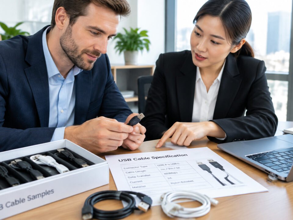
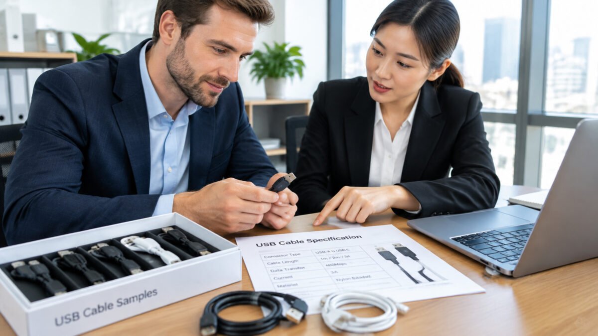
The first step is collecting and clarifying what the cable needs to do. This stage defines the technical scope so that the later design stage has a complete and consistent basis. A clear requirements sheet saves time downstream by reducing misinterpretation and rework. Four areas are confirmed in this stage.
- Application — Where the cable will be used, and how it will be handled in daily operation. This determines the mechanical and environmental demands, such as flexing frequency, temperature range, exposure to liquids, and how the cable is routed and secured.
- Connector — Which plug and receptacle types are needed, on which ends, with which orientation, and whether locking or strain-relief features are required at each end.
- Power Requirement — The required voltage, current, and charging method, including USB Power Delivery where applicable. These guide the conductor size, connector selection, voltage-drop limits, and any required electronic marking.
- Data Requirement — Whether the cable is for charging only or must also support data transfer, and the required USB standard and data rate. Video support, if needed, is confirmed separately. The wiring, shielding, and signal performance are evaluated for the specified length.
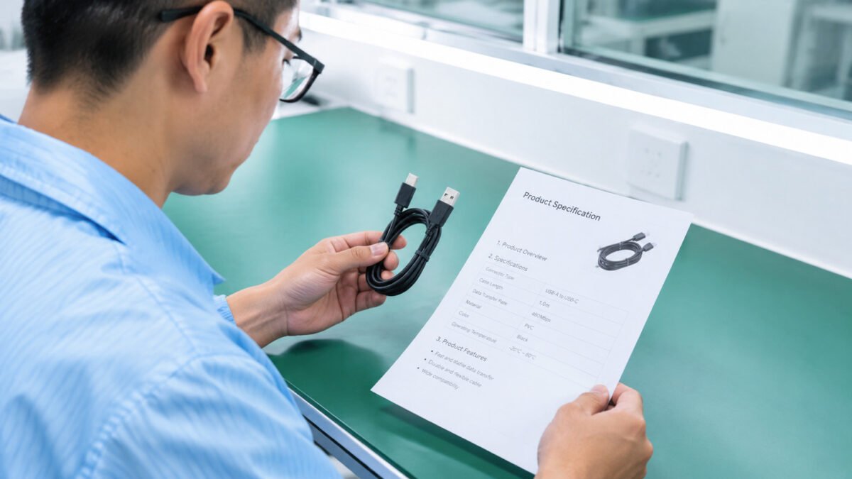
At the end of this step, a requirements sheet is compiled. It records the target specifications, intended use, and applicable compliance notes, and it is used to check the design and the finished product against the agreed project specification. Cable length and tolerances, branding, packaging, estimated order quantity, and target timing are also confirmed at this stage. The sheet forms the basis for quotations and for the delivery schedule, so the buyer and the factory agree on the target before engineering work begins.
2.2 Step 2: Engineering Design
With requirements defined, the engineering team converts them into a manufacturable construction. The design stage decides how the cable will be physically built so that it can meet the recorded specification during production. Three areas are addressed in this stage.
- Cable Structure — The arrangement of conductors, the number and gauge of the wires, the presence and type of shielding, and the overall jacket and outer diameter. The structure balances installation flexibility, conductor sizing for the required current, and shielding appropriate to the data and interference requirements.
- Material — The conductor material, the insulation, the jacketing (such as PVC, TPU, or silicone, available on selected models), and flame-retardant or low-smoke grades required for the application. Material choice is based on the operating temperature, flexibility, chemical exposure, and applicable compliance requirements of the target market.
- Connector — The connector bodies, contact plating, and housing style, selected to match the connectors confirmed in the requirement stage and sized to the cable construction.
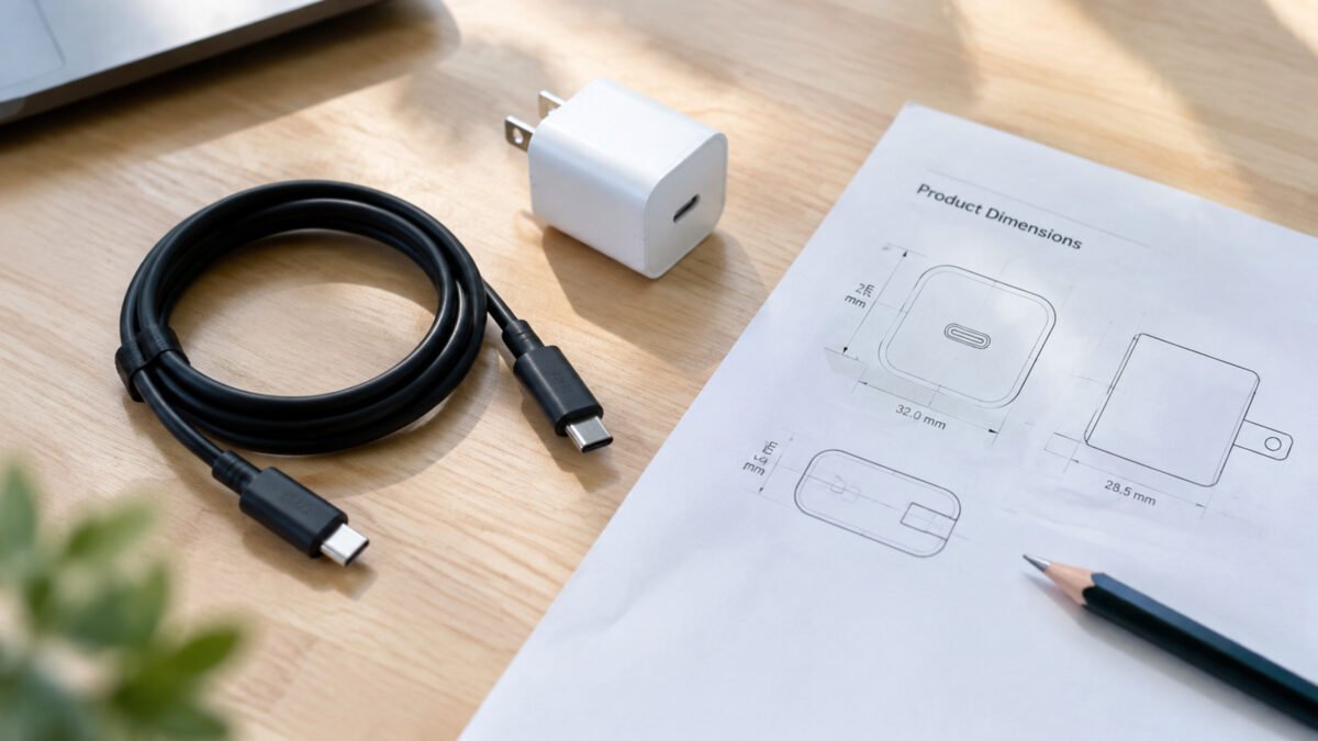
The output of this stage is a technical drawing and a bill of materials. These documents define the key components, dimensions, and tolerances, so that the prototype in the next stage can be produced consistently and evaluated against a fixed specification rather than guesswork. With the bill of materials in place, the required materials and connector parts can be identified and ordered, and the manufacturing method for the selected construction can be confirmed before tooling is prepared.

2.3 Step 3: Prototype Development
Before entering mass production, samples are produced to verify that the design works as specified. This stage catches issues while changes are still inexpensive, and it gives the customer a physical example to confirm and approve.
- Sample Production — A small run of cables is built to the latest design drawing, using the same materials and processes intended for final production, so the customer can evaluate the proposed construction before mass production.
- Testing — Samples are checked against the recorded requirements. Typical checks include electrical continuity and resistance, connector engagement and fit, data transmission at the rated speed, and mechanical checks such as bend and pull strength, on the basis of the applicable standard. The exact test list is matched to the requirements defined in Step 1.
After sample review, required changes are recorded and the drawings are updated. Revised samples or additional test results are provided where needed. Mass production begins after the customer approves the final sample and specification. The approved sample becomes the reference for the production stage and is retained so later lots can be compared against it. Where a requirement cannot be verified by eye, the relevant test result is attached to the sample record, so the approval decision is based on measured data rather than appearance alone.
2.4 Step 4: Mass Production
Once the prototype is approved, the project moves into volume manufacturing. This stage focuses on delivering consistent quality at the required volume and on schedule, and on protecting the specification established during the earlier stages.
- Production — Cables are assembled in volume using the approved drawing and bill of materials, following the standard process defined for the selected construction. Production tooling and fixtures keep the assembly consistent from lot to lot.
- Quality Control — Incoming materials, in-process checks, and final inspection follow the agreed quality plan. Routine electrical checks and sample-based performance or mechanical tests are carried out as specified for the project.
- Delivery — Finished goods are packed according to the agreed specification and are shipped to the destination on the agreed schedule, with the required documentation to support the buyer's receiving and inventory processes.
The approved sample, drawings, and inspection criteria provide the reference for controlling quality across production lots and repeat orders. The same flow can be followed for repeat orders, using the established specification as the starting point for the next run.
3. Related Topics
The following guides can help buyers select and specify a custom USB cable for their project.
- USB Cable Solutions
- USB Cable Specification Guide
- USB Cable Selection Guide
Discuss Your Custom USB Cable Project
To start a project, send the application, connector types at both ends, required length, power and data requirements, operating environment, and estimated order quantity. Include a drawing, device specifications, or photos of the mating ports where available. Send us these details so we can review your requirements and confirm feasible options, sample arrangements, and quotation details.