

Custom USB Charger Manufacturing Process
2026-09-17
Custom Power Adapter Manufacturing Process
2026-09-18
Product Design & Engineering Support
Product Design & Engineering Support
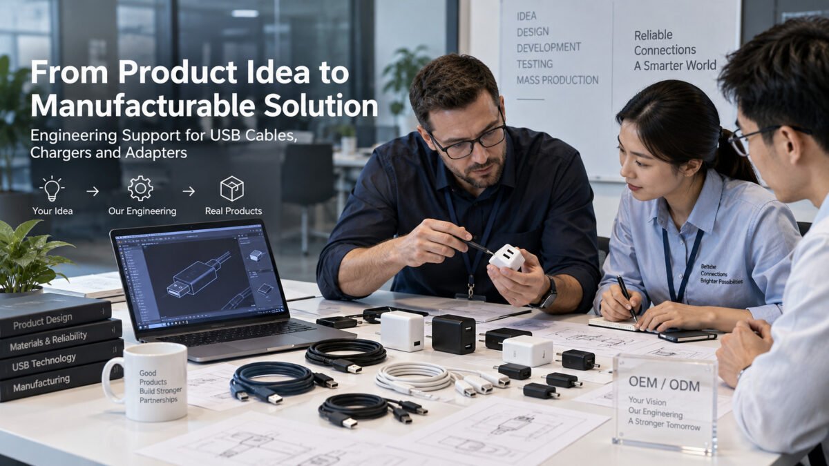
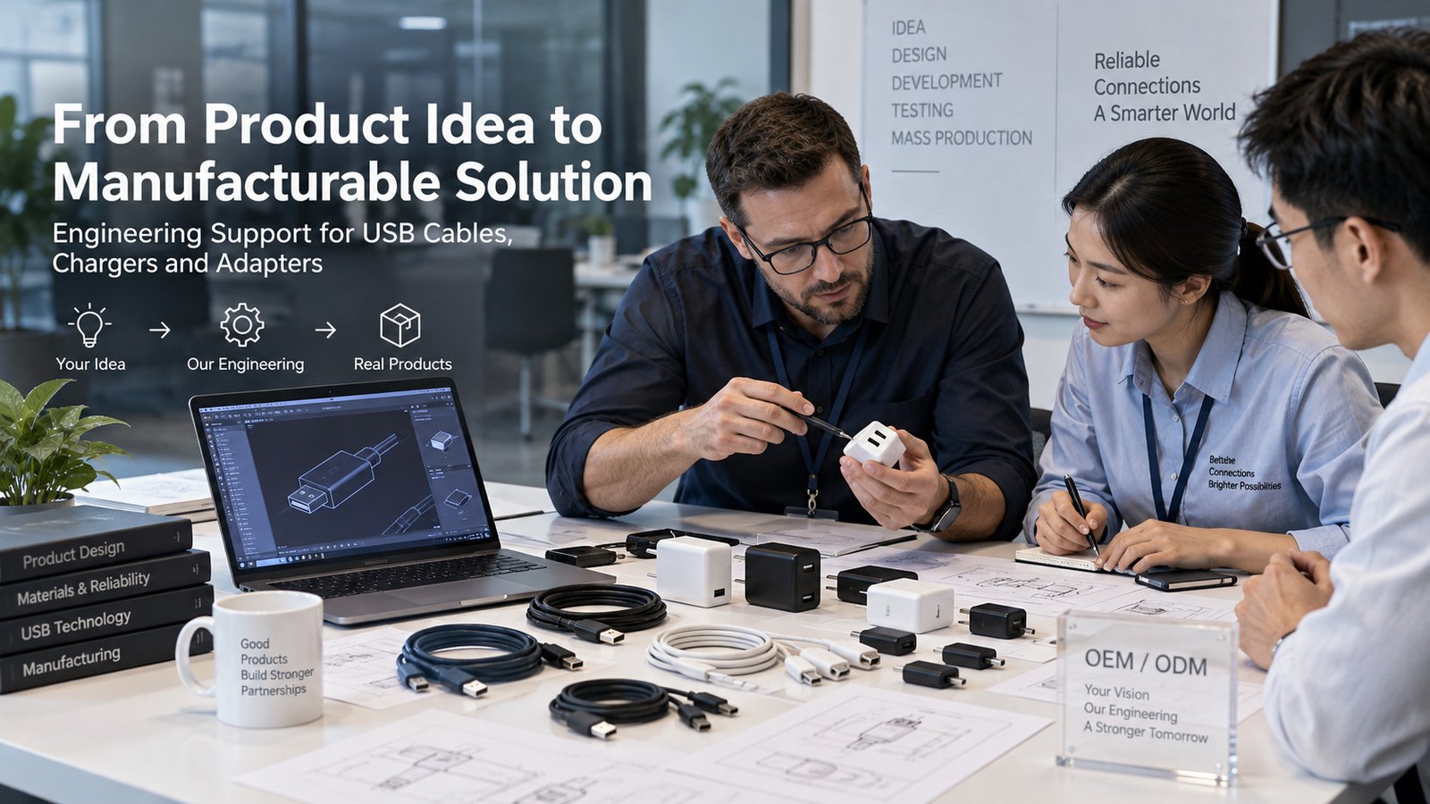
Turn a product idea into a manufacturable USB cable, charger or adapter with structured engineering and design support. Many buyers hold a clear product idea but lack the in-house engineering resources to turn it into a manufacturable item. This page describes the engineering support and design support available across USB cable, charger and adapter programs. The intent is to help procurement teams, brand owners and industrial customers understand how a concept moves from a description to a production-ready specification, and what can be done during the process to keep performance, reliability and cost in balance.
1. Engineering Support
Engineering support covers the technical decisions that must be made before tooling and production begin. It is structured around three stages: understanding the requirement, converting it into a measurable specification, and refining that specification so the product can be built consistently and at a reasonable cost.
1.1 Requirement Analysis
Requirement Analysis is the first stage, in which the intended use of the product is clarified. Typical questions resolved here include the form factor of the connector, the cable length and outer diameter, the power capacity the product must carry, and the environments in which it will be used. For example, a cable intended for fixed desktop installation may not be required to withstand frequent flexing, while a cable used with a portable device may need a more flexible jacket and reinforced strain relief.
The analysis also covers the target data and power performance. For a USB cable, this means confirming whether the design should target a high-speed data application or a power-only application, and whether it should support fast-charging power levels. These choices are recorded as clear, testable targets rather than assumptions. Where a requirement is ambiguous, it is flagged early so that a wrong specification is not carried into the later stages.
Output at this stage typically includes a documented list of functional requirements, the application conditions, the applicable compliance and safety obligations for the destination market, and a preliminary cost and schedule estimate. This document becomes the reference point that the remaining stages are checked against.
Structured analysis is particularly valuable when a project exists only as a general concept. Instead of guessing at a design, the requirement list makes each decision explicit, which helps avoid mismatches between the intended product and the eventual specification. This is useful for brand owners introducing a new accessory line, and for industrial customers integrating a cable or power accessory into a larger product where the interface and electrical load are already defined.
1.2 Specification Definition
Specification Definition converts the analyzed requirements into measurable engineering parameters. Electrical parameters such as rated current, resistance and impedance are defined with targets and acceptable tolerances. Mechanical parameters such as connector dimensions, cable gauge, and mating force are set. Environmental expectations covering temperature range and mechanical durability are also assigned a concrete test method.
For USB-related products, the specification references the applicable standards and product requirements according to the connector type, power rating, data function and destination market. This helps ensure that electrical limits, mechanical fit and compliance expectations are considered during design. Parameters are stated as design targets with stated tolerances rather than as marketing claims, so that verification is meaningful during sampling.
Once defined, the specification is reviewed with the customer to confirm that the measurable values match the market expectation. Sign-off at this point reduces rework in later stages, because tooling and process decisions are made from a fixed set of parameters.
A well-formed specification also serves as the basis for inspection during production. When each parameter has an assigned test method and tolerance, quality control can be exercised against the same targets used at the design stage, rather than against an informal description. This linking of design targets to test plans is a central value of the specification stage.
1.3 Product Optimization
Product Optimization reviews the defined specification against manufacturing reality before tooling is finalized. The goal is to identify areas where the same performance can be achieved at a lower cost, or where a design detail may create a difficulty in mass production that can be corrected in advance.
Typical activities include reviewing connector assembly tolerances to avoid fit issues, adjusting cable layer design to improve yield, and simplifying construction steps without reducing reliability. Optimization also evaluates substitution of materials that keep the specified electrical performance while improving cost or availability. The result is a refined version of the specification that remains within the customer's functional requirements but is easier to build consistently.
This stage is iterative rather than a single correction. Each proposed change is checked against the original requirement list, so the product does not lose a feature purely for the sake of cost reduction. Optimization therefore sits between design and production: it closes the gap between what is specified on paper and what can be manufactured at an acceptable yield and cost.
2. Design Support
Design support addresses the physical construction of the product, from the structure and materials to ongoing improvements after a design has been released. It complements engineering support by focusing on how the product is put together and how it can be improved over time.
2.1 Structure Design
Structure Design covers the mechanical layout of the product, including the connector shell and retention features, the cable construction, and the strain relief at both ends. The arrangement of these parts determines how the product performs under plugging, pulling and flexing, and how evenly mechanical stress is distributed.
For cables, structure design chooses the number of layers, the braiding or shielding arrangement, and the way conductors are laid so that the finished cable has the required flexibility and structural strength. For chargers and adapters, structure design addresses the enclosure, the arrangement of internal components, and the heat dissipation path. Dimensional details such as plug tolerances and connector shell fit are set to support consistent assembly in production.
Structure design is carried out with manufacturability in mind, so that the mechanical layout can be produced with the available tooling and assembly methods rather than requiring an impractical process. Key mating and retention dimensions are controlled within defined tolerance ranges to support consistent assembly and reliable fit in mass production.

2.2 Material Selection
Material Selection chooses the materials for conductors, insulation, shielding, jacketing, contacts and enclosures. The selection is made against the electrical, mechanical and environmental requirements defined in the specification, and against cost.
Conductor material and strand count affect current-carrying capacity and flexibility. Insulation and jacket compounds affect temperature rating, flex life and external appearance. For connectors, the choice of contact material and plating influences contact resistance and durability over repeated cycles. Material choices are based on documented performance data rather than on general descriptors, and the selected grade is confirmed to be consistently available for production.
Where a material affects compliance, the applicable safety and environmental obligations for the destination market are taken into account. Any alternates considered for cost reasons are verified to retain the specified mechanical and electrical behavior before substitution. Because material cost is a major share of accessory production cost, the selection process weighs long-term availability and temperature performance as well as the initial unit price, so the chosen grade remains stable across production batches.
2.3 Product Improvement
Product Improvement covers incremental changes made after a design has entered production. Feedback from assembly lines, test results from incoming inspection, and returns or field performance observations provide inputs that drive controlled improvements to construction, material or process.
Improvement work is governed by the same discipline as the initial design. Proposed changes are measured against the original specification, tested in samples, and reviewed before being adopted, so that an improvement in one area does not reduce performance in another. This approach suits products that need to adapt to changing accessory configurations or to evolving market preferences while keeping a stable core design. Because improvement is continuous rather than a single event, products can be refined based on real production and usage data while the controlled process keeps the change from introducing new risks.
3. Applicable Products
The engineering and design support described above applies to a defined range of accessory products. These programs share a common approach of starting from the customer's requirement and following the stages of analysis, specification and optimization.
3.1 Cable
USB cable programs cover charging cables, data cables and combinations of both. Support addresses the connector combination, the cable length and diameter, and the electrical rating the cable is required to carry. Cable construction is defined for the intended use, including the layer arrangement and jacket flexibility suitable for portable or fixed applications. Selected models can be produced with additional shielding where a design requires it. Because a cable is defined as a finite set of parameters rather than a single fixed item, the structure stage can be used to develop a family of related lengths and connector variants from one base design. Typical selection factors for a project include connector combination, charging current, data function, cable length, outer jacket material, flexibility, shielding requirement and usage environment.
3.2 Charger
Charger programs apply engineering and design support to power delivery accessories. Work covers the definition of the rated output, the enclosure structure, the arrangement of internal components, and thermal management for sustained operation. Structure design and material selection are carried out together, with attention to assembly consistency and compliance with the safety obligations of the target market. Requirement analysis first establishes the output requirement and the plug configuration for the destination region, so the electrical and mechanical design are defined from a shared starting point.
3.3 Adapter
Adapter programs combine mechanical design with electrical definition for products that connect different interface formats and meet defined power or signal requirements. If active conversion or protocol support is needed, these functions are specified and verified separately. Requirement analysis identifies the source and destination interface and the power handling the adapter must support. Specification definition sets the mechanical and electrical parameters, while structure design and material selection ensure the adapter fits and performs reliably through repeated connection cycles. A wide range of adapter configurations can be developed within the same structured process. Because the adapter interface is the link between two devices, its retention and contact design receive particular attention to keep connection stable under repeated use.
Each product type follows the same documented path. This keeps expectations clear, supports effective communication between the buyer and the engineering team, and results in products that can be built consistently and verified against their specification.
Project Inquiry
Share the connector type, power rating, data function, cable length, material preference and target application. A requirement shared in this detail can be reviewed and developed into a manufacturable specification through the engineering stages described on this page.
Available functions, ratings and materials depend on the confirmed specification, target application and test requirements. Electrical parameters are stated as design targets during development, and final ratings are confirmed against the relevant standard before release.