

Electronics Manufacturing Capability Overview
2026-09-19power-adapter
2026-09-21
USB Cable Guide – Article Stylesheet
USB Cable Manufacturing Process and Capability
An overview of the controlled USB cable manufacturing process, the range of cables produced, and the customization options supported for bulk, OEM and ODocus purchasing.

1. USB Cable Production Process
This overview covers the main controlled stages for the applicable cable design: incoming material control, cable preparation and termination, connector assembly and molding, electrical inspection, and final release. Operations such as conductor stranding, insulation or jacket extrusion, shielding, and packing are described only where they are performed or controlled for the relevant product. Outputs are checked against the applicable specification at the inspection points defined for the relevant cable design before release to the next controlled operation.
1.1 Material Preparation
Material preparation is the stage in which raw materials entering the production line are inspected, organized, and prepared for downstream assembly operations. It ensures that the cable conductor, insulation, and connector components are consistent in specification and suitable for the product being produced.
1.1.1 Cable Material
Cable material refers to the primary conductive and structural components of the cable, mainly the conductor and the insulation. Conductors are typically made from annealed copper wire, which provides good electrical conductivity for signal and power transmission. The conductor is commonly formed into multiple fine strands to improve flexibility, so that the cable can bend and flex during normal use without fracturing. The wire gauge and strand count are selected according to the current-carrying requirement and the flexibility target of each cable design.
The conductor is protected by an insulating layer, usually made from a thermoplastic material. The insulation material is chosen based on its dielectric properties, flexibility, and temperature rating for the intended application. During preparation, the insulated conductors are checked for dimensional consistency, surface quality, and continuity. Materials that do not meet the defined specification are set aside before they enter the assembly line, so that only suitable material progresses to the next stage.
1.1.2 Connector Components
Connector components are the parts that establish the interface between the cable and the devices it connects. These include connector shells, contacts or terminals, and other inner components required for structural support. For USB connectors, the contacts are arranged according to the applicable pin configuration, and the shell provides mechanical protection and alignment.
Connector components are inspected for dimensional accuracy, plating quality, and surface finish before assembly. Contact plating and base materials are selected according to the approved connector specification and the required contact and corrosion performance. Components are kept in clean, organized storage and handled to avoid surface contamination or physical deformation. Material preparation therefore acts as a quality gate, confirming that the connector components are suitable before they are joined to the cable.
1.2 Cable Assembly
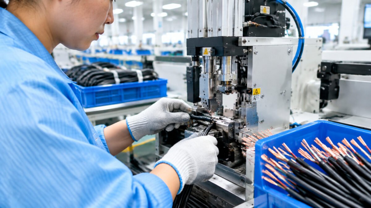
Cable assembly is the stage in which the prepared cable material and connector components are joined to form a complete interconnect assembly. This stage consists of the cutting, assembly, and connection operations, each of which contributes to the mechanical and electrical properties of the final product.
1.2.1 Cutting
Cutting is the operation that determines the cable length and prepares its ends for subsequent assembly. The cable is cut to the agreed nominal length and tolerance for the selected design, so that the finished cable matches the customer’s application requirement. Precise cutting with controlled tolerance also helps keep the output of each order uniform.
In addition to cutting the cable to length, the ends are stripped to expose the appropriate amount of bare conductor for the subsequent connection operation. Cutting and stripping are performed to controlled tolerances, because the length of the stripped section directly affects how securely and reliably the electrical connection can be made. Off-specification cuts are detected and rejected early, keeping the downstream operations efficient.
1.2.2 Assembly
Assembly is the operation in which the cut and stripped cable ends are combined with the connector components to form the mechanical structure of the cable assembly. The cable and connector are positioned and held in place, and the internal components are arranged so that the electrical connections can be made.
At this stage, attention is given to the alignment of the contacts with the conductor ends, the routing of the conductors within the connector housing, and the overall fit of the components. Correct assembly geometry supports reliable performance and consistent dimensions in the finished connector. Assembly is carried out by trained operators or automated equipment according to the volume and design of the order, using controlled methods that support repeatable results.
1.2.3 Connection
Connection is the operation in which the prepared conductor ends are joined to the connector terminals. Depending on the connector design, conductors are terminated by crimping, soldering, or an approved terminal assembly or board assembly. For crimped designs, crimp quality and pull force are controlled according to the applicable specification, and additional crimp performance claims are made only when supported by validation data.
Crimp quality is monitored during the connection stage, because a consistent crimp is important for reliable electrical contact and mechanical retention. In designs where a soldered or board-based joint is required, the applicable joining method is applied and verified. After the connections are made, the assembled unit proceeds to overmolding where specified, or to the applicable connector housing assembly process. The connection area is then protected and mechanically supported according to the selected design.
1.3 Connector Housing and Molding
After connection, the connector area is enclosed and supported by one of two controlled approaches, depending on the cable design. For overmolded designs, injection molding forms a protective body around the connector. For designs that use a separate housing assembly, the connector housing and related components are assembled with the cable, and housing fit, alignment, and mechanical retention are checked against the approved design requirements. In both cases, the process parameters and inspection points are defined for the applicable design, because the choice affects the durability and dimensional consistency of the final connector.
1.3.1 Connector Molding
For designs that use overmolding, a thermoplastic resin is injected into the mold cavity, where it flows around the connector components and hardens into the required shape. The overmolded body supports and protects the connection area. The level of dust or moisture resistance depends on the material, tool design, interface construction, and validation testing; no IP or waterproof claim is made unless it is supported by product-specific test data.
The molding process is controlled for material temperature, injection pressure, and cooling time, so that the molded part has consistent density and dimensions. The final molded connector is checked for surface defects, visible voids, flash, and correct overall dimensions.
1.3.2 Strain Relief
For overmolded designs, strain relief is formed at the point where the cable exits the connector body. Its purpose is to distribute the mechanical stress that occurs when the cable is bent, pulled, or handled during use, so that repeated flexing at the cable exit does not place excessive stress on the internal connections.
The strain relief is designed to allow controlled bending of the cable while transferring load away from the connection point. Its geometry and material are selected according to the intended application and applicable flex or pull requirements. Where durability is claimed, it is associated with defined flex or pull test conditions for the applicable model.

1.4 Testing
Testing is the stage in which the assembled cable is verified against defined electrical and performance criteria before release. Testing is carried out according to the approved inspection and test plan for each SKU. The test methods and their frequency are defined for the applicable product and are not assumed to be identical across cable designs.
1.4.1 Electrical Test
Electrical testing verifies the electrical characteristics of the cable assembly. In-line checks may include 100% continuity, open/short, and pinout verification, depending on the approved inspection plan. Insulation resistance and conductor resistance are checked at the frequency defined for the applicable product and test plan. Units failing applicable electrical tests are segregated for disposition.
1.4.2 Performance Test
Performance testing evaluates the cable under conditions that reflect its intended use, at the coverage defined in the approved product and test specification. Where specified for the applicable SKU, signal-integrity, current-carrying, thermal, insertion and withdrawal, flex, and pull performance is evaluated against the agreed product and test requirements. Test results are reviewed against the product specification before release. Performance tests are applied as 100% or sample-based tests according to the approved inspection plan.
2. Manufacturing Capability

The manufacturing capability covers a range of USB cable types, each configured to suit a different set of performance and application requirements. The production capability uses a controlled process framework, with operations and equipment selected according to the construction and requirements of each cable type.
2.1 USB-C (USB Type-C) Cable
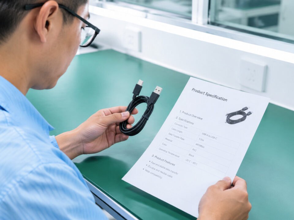
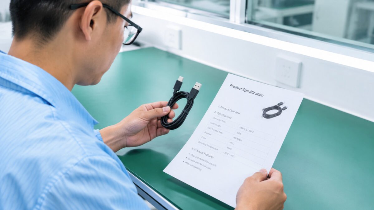
USB-C cables use a USB Type-C connector at one or both ends. Data performance, charging capability, rated power, video support, and E-Marker configuration depend on the cable design and the connected host, charger, and device. SKU specifications identify the connector combination, data capability, rated current or power, length, and applicable compliance requirements. USB-C cables are available in the length range offered for the selected design and can be configured with approved connector combinations.
2.2 High-Power Cable
High-power cables are designed to a specified current and power rating. Conductor cross-section, contact design, cable length, insulation, and, where applicable, E-Marker and USB Power Delivery requirements are selected and validated for the target SKU. The stated rating applies when the cable is used with a compatible charger, host, device, and compliant components. Laptop and tablet charging capability depends on the complete system rather than the cable alone.
2.3 Industrial Cable
Industrial-oriented USB cables can be configured with jacket, shielding, connector housing, and strain-relief materials selected for the specified environment. Resistance to flexing, moisture, dust, temperature, chemicals, or vibration is stated only for models with corresponding design criteria and test evidence. Suitable use in equipment or instrumentation depends on confirmation of the interface, electrical rating, and environmental requirements.
3. Customization Capability

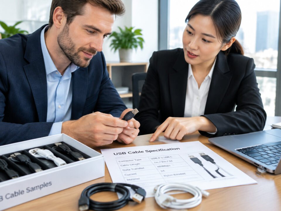
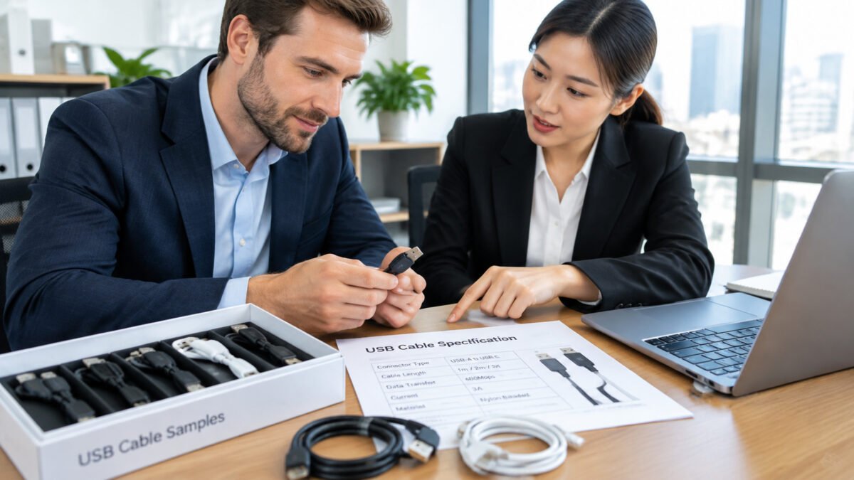
The customization capability allows a cable order to be configured to match the specific requirements of the customer’s application. Customization is offered across four main areas: length, material, connector, and appearance. Custom options are subject to the selected design, tooling, MOQ, material availability, and validation requirements.
3.1 Length
Cable length can be produced to the agreed nominal length and tolerance for the selected design. Consistent length control during cutting ensures uniform output across the order, and the finished length can range from short interconnects for compact devices to longer cables for setups where the connected devices are farther apart.
3.2 Material
Material options are selected from approved conductor, insulation, shielding, and jacket specifications. Material changes are subject to design review, availability, and validation for the required electrical and mechanical performance. Material selection can be used to balance factors such as flexibility, durability, and suitability for the operating environment, within the approved specification range.
3.3 Connector
Connector options include the connector type, orientation, housing, and wiring configuration available for the approved design. Contact assignments and wiring must follow the applicable USB or product specification, so that the interface is built to the required standard. Connector customization allows a cable to be produced for a specific combination of source and destination devices, such as connecting a USB-C port to a standard USB-A port.
3.4 Appearance
The appearance of the cable can be customized to match the customer’s product identity or application preference. Appearance options may include the color of the cable jacket, the color of the connector body, and the finish of the molded components. Branding or identification markings can also be applied in a controlled manner. Appearance changes are reviewed against the selected design. Changes that may affect electrical, mechanical, or environmental performance are validated before production.
4. Conclusion
The USB cable manufacturing process is organized into controlled stages, with the operations, inspection points, and test coverage defined for the applicable cable design and specification. The manufacturing capability covers USB-C cables, high-power cables, and industrial cables, and the customization capability extends the range of order-specific options in length, material, connector, and appearance. These capabilities allow USB cables to be produced to meet a wide range of application requirements within validated design and specification boundaries.
Discuss Your USB Cable Requirement
For bulk USB cable procurement, OEM and ODM projects, or custom configurations across length, material, connector, and appearance, the controlled manufacturing process supports a wide range of application requirements. Share your target cable specification and application details to evaluate a suitable configuration.