

Product Design & Engineering Support
2026-09-18
Product Selection Tool: Requirements to Recommended Product
2026-09-18
Custom Power Adapter Manufacturing Process
Custom Power Adapter Manufacturing Process
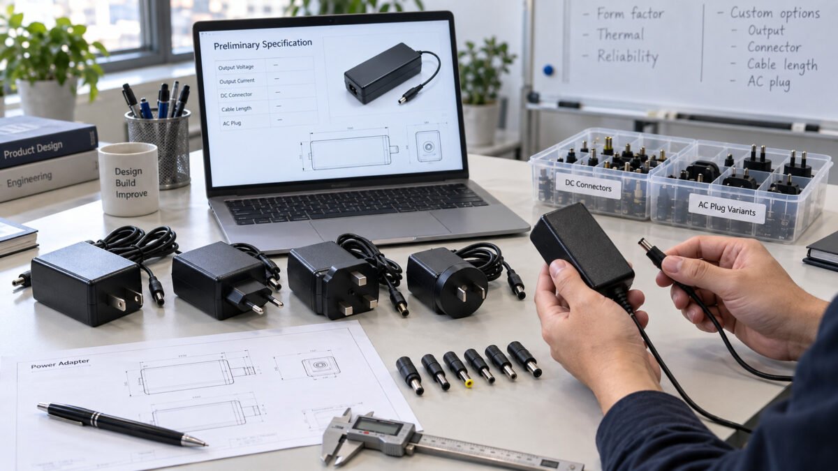
A custom fixed-output power adapter is developed around the electrical, mechanical and compliance requirements of the target device. Unlike USB Power Delivery and other negotiated-output systems, a conventional fixed-output adapter supplies a specified DC output without negotiating voltage with the connected device. Output voltage, current capability, connector, polarity, cable configuration and applicable market requirements therefore need to be defined before development begins. The path from that definition to a mass-produced adapter follows a defined sequence: requirement analysis, engineering design, prototyping, validation and production, with each stage documented so the finished unit can be traced back to the agreed specification and confirmed against the device it serves.
1. Custom Requirements
A custom adapter requirement defines the electrical and mechanical interface that the device expects. Because a fixed-output adapter does not negotiate, each parameter must be correct as a set. The voltage determines the required output level, the current capability determines what the adapter can supply under load, the wattage expresses the available output power, and the connector and polarity define the physical and electrical connection to the device. AC input and plug configuration are selected alongside these parameters according to the destination market.
1.1 AC Input and Plug Configuration
AC input range and plug configuration are selected according to the destination market and the specific adapter design. Available configurations depend on the selected model and project requirements, and the input voltage range and any regional plug variant are confirmed against the target market before design. For programs serving multiple regions, the input coverage and the required plug or interchangeable options are reviewed together.
1.2 Output Voltage
The output voltage must fall within the device’s specified input range. The nominal output voltage is confirmed from the device specification and input rating rather than inferred from a similar-looking adapter. Where the device specifies an allowable input range or tolerance, the adapter output is evaluated against those limits under the defined load and input conditions.
Because the adapter does not negotiate, the voltage should not be assumed from the connector size or appearance. For a selected model, the delivered output voltage under the defined input and load conditions is part of the specification reviewed with the device.
1.3 Current
The adapter provides a rated output current capability, and the device draws what it needs up to its own demand. The rated current capability must meet or exceed the device’s maximum requirement, so the adapter is not sized down to a typical load where peak or startup demand could exceed it. The sustained current under the required duty cycle and operating temperature is confirmed against the device.
Current capability is reviewed together with the output voltage, connector and polarity rather than on its own. A capability higher than the device demand is acceptable, provided the voltage and polarity are correct, and the rating is documented for the produced configuration.
1.4 Wattage
Wattage expresses the output power the adapter can sustain, combining the rated voltage and the rated current capability within the adapter’s operating conditions. The required wattage is set by the device’s maximum power demand and any margin established from the equipment specification and intended duty. Wattage alone does not define an adapter, because the voltage and connector must still match the device.
Wattage is also relevant to compliance and thermal behavior. Higher-output units are reviewed for internal temperature under rated load, and the rated output is documented with the input and environmental conditions under which it applies.
1.4 Connector
The DC output connector must match the device input in geometry, dimensions, pin configuration and polarity. For barrel-type DC connectors, parameters such as outer diameter, inner diameter and center-positive or center-negative polarity are confirmed against the device specification, because a correct voltage with an incompatible connector still prevents operation. Where a cable is integrated or removable, the conductor size and length are reviewed for voltage drop against the operating current.
Polarity is confirmed together with voltage and current, and a defined connector and cable length forms part of the specification. Any custom connector or cable option is validated with the target device before the design is finalized.
2. Information Required for a Custom Adapter Project
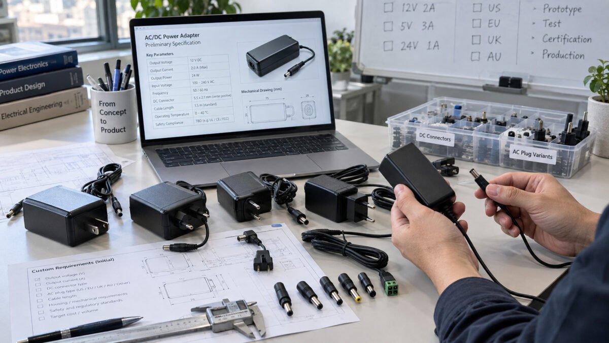
Providing a defined set of inputs at the start helps a custom adapter project move from requirement to quotation efficiently. The details allow the platform choice, development scope, sample plan and validation items to be confirmed before design begins. A typical project specification covers:
Output voltage, maximum load current and required output power; DC connector type and polarity; cable length; AC input range and AC plug type; operating environment; destination market; required certifications or compliance scope; estimated order quantity; and housing, label and packaging requirements. Details such as the target device model and the intended duty are also useful, because the adapter output is confirmed against the device input and the load it will serve.
2.1 Development Process
The custom adapter development process moves a requirement through requirement analysis, engineering design, prototyping, validation and production. Each stage produces a defined output that the next stage builds on, so that a dedicated adapter can be traced back to the agreed specification. The depth of each stage depends on whether the project uses a standard platform, a modified design or a fully custom build, and the process is sized to the risk and scope of the program.
2.2 Requirement Analysis
Requirement analysis establishes what the adapter must do before design begins. The device input is reviewed to define the output voltage, the current capability, the connector geometry and the polarity, together with the input supply for the region, the operating environment and the applicable compliance path. The requirement also covers the load profile, the duty and whether the device runs continuously or intermittently.
A documented requirement covering voltage, current, connector, polarity, input, environment and regulatory scope is the reference for the stages that follow. Ambiguities are resolved before design so they do not propagate, and any assumption about the device input is confirmed against the specification rather than left open.
2.3 Engineering Design
Engineering design turns the approved requirement into a manufacturable design, working across the electrical and the mechanical sides. Electrical design covers the power conversion, the supported input range, output regulation and stability under load, and the protection functions such as overvoltage, overcurrent, short-circuit and overtemperature protection where provided on the selected model. The design targets the rated output within the defined input and environmental conditions.
Housing design covers the enclosure, its size, finish and construction, thermal management, and the connector or cable exit arrangement for the intended use. Higher-power units require evaluation under sustained rated load, because excessive internal temperature can reduce reliability or activate power derating or thermal protection. Ingress protection, drop resistance and cable management are reviewed where relevant to the application.
The mechanical design must allow the electrical design to operate within its thermal limits and meet the intended installation requirements. The two design streams are reviewed together so the complete unit is coherent, and inputs and outputs are recorded against the specification before sampling.
2.4 Prototype
Prototyping produces physical units against the design so the adapter can be tested rather than assumed correct. The sample confirms that the unit can be assembled as designed and that the mechanical and electrical elements fit together, including the enclosure, the PCB, the connector and any cable. The sample build also reveals manufacturability issues that must be corrected before a repeatable process is established.
For a fixed-output adapter, the prototype verifies the delivered voltage under the defined input and load, the behavior at the rated current capability, and the mechanical fit with the target device based on the connector, polarity and cable length defined in the requirement.
2.5 Validation
Validation tests the sample against the requirements for output, thermal performance and mechanical integrity. For an adapter, this includes confirming the output voltage and current capability under the defined input and load conditions, the protection response where provided, and the temperature behavior under sustained rated load. Compatibility checks use the intended device and connector so the result reflects the real installation.
Where a sample does not meet the requirement, the design is revised and a new sample is reviewed before production. The applicable compliance path is confirmed during this stage, and the required reports, certificates, declarations, markings or registrations, as applicable, are identified for the final configuration. The validated sample then becomes the reference for production, which is intended to reproduce the behavior that validation has established.
Produzione
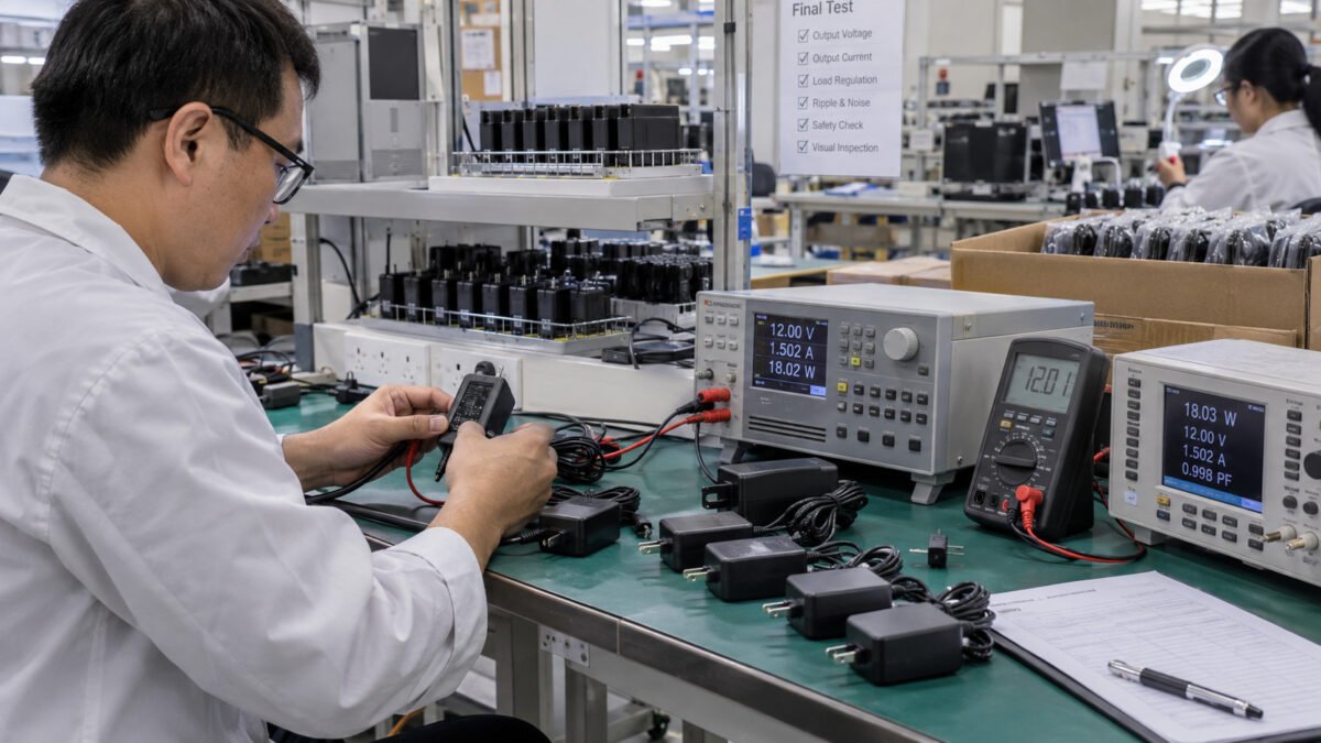
Production moves the validated design into repeatable output at the required volume. Mass production is controlled through approved specifications, materials, tooling, work instructions and test criteria. The exact combination of 100% routine tests and sampled inspections depends on the product design, applicable requirements and agreed quality plan.
Quality control is applied to incoming materials, in-process production and finished units. Depending on the control plan, adapter checks may include output voltage, load performance, protection response, mechanical inspection and the electrical-safety tests required for the model and destination market. Test items and acceptance criteria are documented for the specific project rather than assumed to be identical across all models.
Mass production is confirmed against the validated sample before shipment, and shipping documents, labels and packaging are prepared according to the approved order requirements.
3. Applicazioni
Custom power adapter programs serve different equipment groups, and the application shapes the specification and the compliance expectations. The device environment, duty and intended market determine how the electrical and mechanical requirements are set, and the appropriate checks and documentation are confirmed for each application.
3.1 Industrial Equipment
Industrial equipment may operate under continuous duty, vibration, wider temperature ranges or increased mechanical stress, depending on the installation. The adapter is selected for the device input rating and its documented environmental conditions, with the rated output under load and the operating temperature range fitting the application. Connector retention, cable robustness and ingress protection are reviewed where the installation requires them.
For a fixed-output industrial adapter, the voltage remains within the device’s specified input range, the connector and polarity match, and the current capability meets or exceeds the maximum device requirement. The compliance path for the destination market is confirmed for the industrial application.
3.2 Medical Device
Medical equipment projects may require additional attention to electrical safety, isolation, leakage current, EMC and risk-related requirements. The applicable requirements depend on the equipment type, intended use, system configuration and destination market.
Where a power adapter is intended for medical equipment, the required safety and EMC standards, isolation requirements and certification scope are defined for the specific project before development. Compliance is evaluated for the final adapter configuration and does not by itself establish compliance of the complete medical device.
Output voltage, current capability, connector, polarity and operating conditions are also matched to the equipment specification. Required test reports, certificates and supporting documentation are confirmed according to the agreed regulatory scope.
3.3 Consumer Electronics
Consumer electronics adapters power devices such as routers, displays, monitors, speakers and other low-voltage DC-powered consumer devices. The specification is set by the output the device requires, the connector it uses and the regional AC input, and the adapter’s rated current capability meets or exceeds the device demand.
For consumer electronics, consistency across a production run and compliance documentation for the destination market are central. The output, connector and labeling are confirmed for the produced configuration, and packaging and compliance markings are prepared to match the retail or distribution requirement.
Start Your Custom Power Adapter Project
Whether you need a fixed-output adapter for industrial equipment, a medical-grade power solution, or a consumer electronics power supply, our team can take your requirement through requirement analysis, engineering design, prototyping, validation and production with quality control at every stage. From standard platforms to fully custom builds, we support custom adapter projects with competitive pricing and flexible MOQ.