

Machine Vision USB Solutions
2026-09-14
Retail Brand Charging Solutions
2026-09-15
Robotics USB Cable Solutions
Robotics USB Cable Solutions for Continuous Motion and Industrial Environments
Robotic and automated equipment depends on reliable data and power connections during repeated motion, vibration, and demanding operating conditions. Typical commercial USB cables may not be designed or validated for continuous flexing, tight routing, abrasion, or industrial exposure. A cable failure can interrupt production and increase troubleshooting and replacement time. This page outlines common robotic cable stresses, suitable USB cable constructions, typical applications, and the information needed to select or customize an assembly.
1. Application Challenges in Robotics
Robotic systems place unusual and repeated mechanical stress on cabling. Unlike stationary equipment, a robot cell moves continuously, flexes its conductors, and transmits vibration from motors and drives into any attached wiring. Each of these conditions acts on the cable differently and affects both service life and signal integrity.
1.1 Continuous Movement
Robotic arms, linear actuators, and mobile platforms repeat the same travel path, in some cases many times per day. A cable routed alongside a moving axis is pulled, pushed, and cycled with each stroke. Over time, this motion can fatigue the copper conductors and the insulation surrounding them. Because fatigue develops internally before it becomes visible, a conductor can fracture without any external sign of damage. The link may then fail at certain positions while appearing to work at others, which can interrupt production and complicate troubleshooting.
Motion also produces a dynamic load that a fixed-installation cable is not necessarily built to absorb. The flex point, where the cable bends as the equipment translates, concentrates mechanical stress. Strain concentrates at this location, the insulation may wear from within, and the conductor can eventually break where the bend occurs. For a moving application, the cable should be constructed so that individual strands can shift and redistribute strain across the bundle rather than fracture at a single point.
For continuous-motion applications, distinguish between the static and dynamic minimum bend radius. Also review the conditions behind any flex-life rating, including bend radius, travel distance, speed, acceleration, temperature, cable-carrier setup, and electrical load. A smaller stated bend radius or a higher cycle figure does not by itself guarantee longer service life; the selected cable must be installed and operated within its specified test and application conditions.
1.2 Bending
When a cable bends, the conductors on the outside of the curve are placed in tension while those on the inside are compressed. Repeated bending, especially below the specified dynamic bend radius, increases cyclic strain in the conductors, insulation, shielding, and jacket and can lead to premature fatigue.
Bending performance depends on the complete cable construction, including conductor stranding, insulation, shielding, jacket material, overall diameter, and routing method. Sharp bends at the connector termination should be avoided, and suitable strain relief should be used to limit localized stress.
Torsion is a separate requirement from continuous bending. For rotating robotic axes, specify the torsion angle, cable length under torsion, movement speed, and expected cycle count. A continuous-flex rating alone does not demonstrate torsion capability; the selected cable must be specifically designed and tested for the required twisting motion.
1.3 Vibration
Servo motors, rolling elements, and the machine structure can transmit vibration to any attached cable. One effect is fretting at the connector mating interface, where micro-movement between the plug and receptacle contacts can gradually degrade the connection over many small displacements. Another is added low-amplitude flexing on top of the cable's primary bending motion, which contributes separate wear not necessarily captured by the main flex-cycle rating.
Vibration-related wear appears at predictable, inspectable locations: where the cable is clamped, where it enters a connector, and along unsupported spans. A clamping system that grips the jacket without crushing the inner conductors, together with a cable whose jacket resists cutting and abrasion, helps mitigate this wear at fixed points. Where the cable is unsupported, shortening the span or adding a secondary strain relief reduces the vibration transmitted into the connector tail.
2. Cable Solutions for Robotics
The challenges above are addressed by a range of USB cable constructions, each tuned to a different balance of flexibility and durability. The appropriate choice depends on the motion profile, operating temperature, and duty requirements of the specific application.
2.1 High-Flex USB Cable
High-flex USB cables are designed for repeated bending and continuous movement. Depending on the model, they may use fine-stranded conductors together with flexible insulation, shielding, and jacket materials selected for dynamic applications.

Available models are specified by their validated maximum data performance, such as USB 2.0 at up to 480 Mbps or a specific USB 3.2 rate of 5, 10o 20 Gbps. USB C describes the connector and does not by itself indicate the supported data rate, video capability, or USB Power Delivery level.
Flex-life figures should be accompanied by their test conditions. Where required, electrical and signal-integrity checks can be performed before and after flex testing. Signal degradation may appear as retransmissions, reduced usable throughput, enumeration failure, or intermittent disconnection.
For cable-carrier applications, use only models suitable for that installation and follow the specified dynamic bend radius, carrier fill, separation, and anchoring requirements. This type of flexible industrial cable is suitable for robotic axes, cable carriers, and other repeated-motion applications.
2.2 Rugged USB Cable
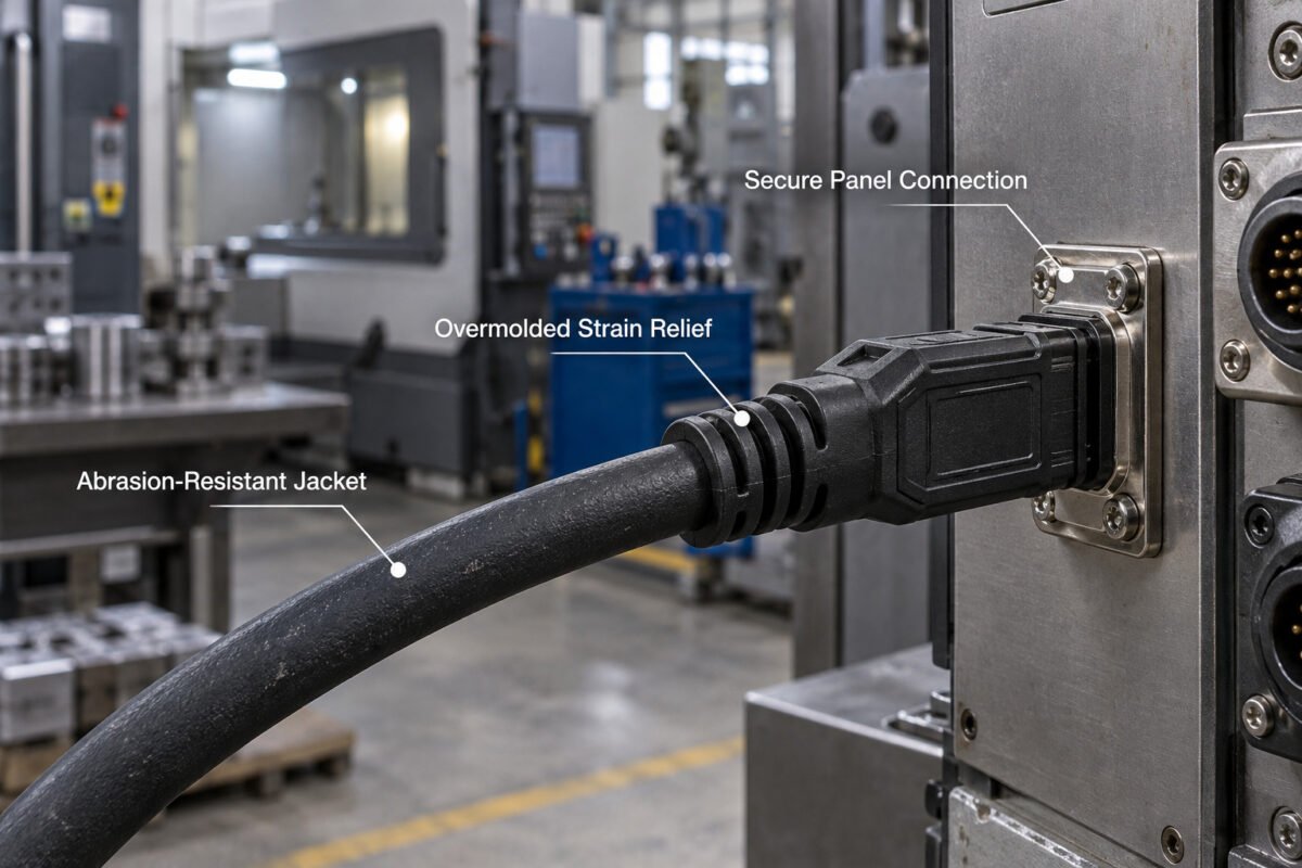
Rugged USB cables are designed to provide additional mechanical or environmental protection. Depending on the selected model, options may include an abrasion-resistant jacket, overmolded strain relief, a robust connector housing, locking hardware, or a sealed panel-mount interface.
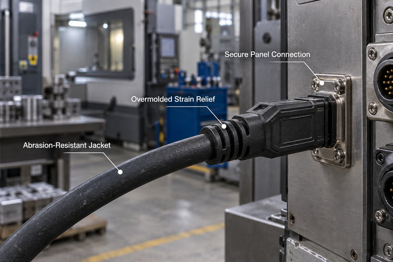
Overmolding can improve strain relief and help protect the cable entry, but it does not by itself establish an IP rating for the complete connection. For dust, washdown, oil, coolant, or chemical exposure, verify the mated connector's IP rating, jacket-material compatibility, operating-temperature range, and applicable test conditions.
Locking connectors, where available, can reduce unintended disconnection under vibration. Secure panel mounting improves mechanical retention, while separate cable support is still required to prevent excessive pulling or unsupported cable loads.
2.3 Custom Cable Assemblies and Options
Custom cable assembly is not a separate alternative to high-flex or rugged construction. Either construction can be customized to match the equipment layout and operating requirements.
Available options may include USB Type-A, USB Type-B, Micro-B, or USB C connectors; straight or right-angle exits; panel-mount or locking interfaces; application-specific lengths; shielding configurations; strain relief; labels; and jacket colors. Connector type, data performance, power capability, and video support must be specified separately.
Selected USB C assemblies may support USB Power Delivery and power levels up to 240 W, depending on the cable construction, electronic marking, connected source and device, and project validation.
Prototype and pilot-order availability, minimum order quantity, tooling requirements, and validation options can be confirmed for your project.
3. Typical Applications
3.1 Robotic Arms
Articulated and SCARA robotic arms route cabling along the arm structure to the end effector, wrist, and gripper. These links bend as the arm traverses its work envelope and experience dynamic loading through each cycle. High-flex cables rated for the application's expected cycle count are a common choice in this role.
Cabling is frequently integrated into a sleeve or wrap along the arm to protect it from abrasion. Because the cable can be exposed at the wrist and gripper, routing and strain relief should keep motion away from the connector termination, reducing the risk of failure at the most heavily stressed point of the run.
3.2 Automation Equipment
Automation equipment includes linear actuators, conveyor systems, pick-and-place units, and test fixtures. These use USB links for programming, sensor communication, and equipment-to-controller connectivity. Rugged cables suit fixed runs near the machine, while high-flex cables suit axes and carriages that translate repeatedly.
Equipment that undergoes periodic reconfiguration benefits from panel-mount USB ports and removable cables, which can shorten cable replacement and maintenance time when an external link needs to be swapped without opening the machine enclosure.
3.3 Smart Manufacturing
Smart manufacturing systems commonly use USB for short, local connections between industrial computers or controllers and devices such as cameras, scanners, HMIs, test instruments, and data-collection equipment. These are typically local device-level connections rather than plant-wide network links.
For these local connections, cable selection should consider data rate, power demand, finished length, EMI conditions, motion, environmental exposure, and maintenance access. Rugged, locking, or panel-mount options may improve serviceability in crowded production environments, while custom lengths and consistent labeling can simplify installation and replacement.
4. Selecting a Robotics USB Cable
Use the following information to identify a suitable standard or custom assembly:
| Selection factor | Information to provide |
|---|---|
| Connettore | USB Type-A, Type-B, Micro-B, or USB C; plug or receptacle; straight, right-angle, panel-mount, or locking |
| Data | Required USB performance, device bandwidth, and whether video or an Alt Mode is needed |
| Energia | Required voltage, current, USB PD profile, and USB C E Marker requirements where applicable |
| Lunghezza | Finished cable length and any routing or space limitations |
| Motion | Static or continuous flexing, dynamic bend radius, travel distance, speed, cable carrier, and torsion angle |
| Ambiente | Operating temperature, abrasion, vibration, dust, washdown, oil, coolant, or chemical exposure |
| Materiali | Jacket material, shielding, flame-rating, and regulatory requirements |
| Validation | Required flex testing, signal-integrity testing, IP testing, inspection reports, or compliance documentation |
For a cable recommendation, send the connector configuration, data and power requirements, finished length, motion profile, minimum bend radius, operating environment, expected order quantity, and any required test or compliance documents.
Need a Robotics USB Cable Solution?
Whether you need standard high-flex or rugged USB cables, or fully customized OEM/ODM assemblies with specific connector configurations, data performance, power capability, cable lengths, strain relief, and environmental protection, our team can help you review the requirements and recommend a standard or custom assembly for your robotic or automation equipment. From USB 2.0 to 20 Gbps, up to 240 W, and static to continuous-flex installations, we support robotics USB cable projects with competitive pricing and flexible MOQ.