


How to Select a Power Adapter: Voltage, Current, and DC Connector
How to Select a Power Adapter: Voltage, Current, and DC Connector
For procurement and engineering teams sourcing a power adapter, the first task is matching the adapter to the device it powers and to the cabling that carries energy into it. Three parameters decide a correct match: voltage, current, and the DC connector. Matching these three parameters is the starting point for electrical and mechanical compatibility. Input requirements, protection features, environmental conditions, and applicable certifications must also be confirmed for the final application. This guide walks through each parameter in turn, then applies the same logic to the recurring purchasing scenarios that come up in real projects.

1. Voltage Selection
Voltage is the electrical pressure a device expects at its input, and it is the first parameter to verify. Current and connector problems tend to produce symptoms you can observe as the load changes; a voltage problem, by contrast, can be present from the first power-on without an obvious warning, which is why it belongs at the top of the checklist.
1.1 Device Requirement
Start with the voltage printed on the device label or stated in its datasheet. This value, expressed in volts (V), is the nominal input the device is designed to accept. Common label values include 5 V, 9 V, 12 V, 19 Ve 24 V, and the figure printed on the label tells you the target the adapter must supply. The device's own documentation is the authoritative source; never infer the input voltage from the look of the product or from the shape of its socket.
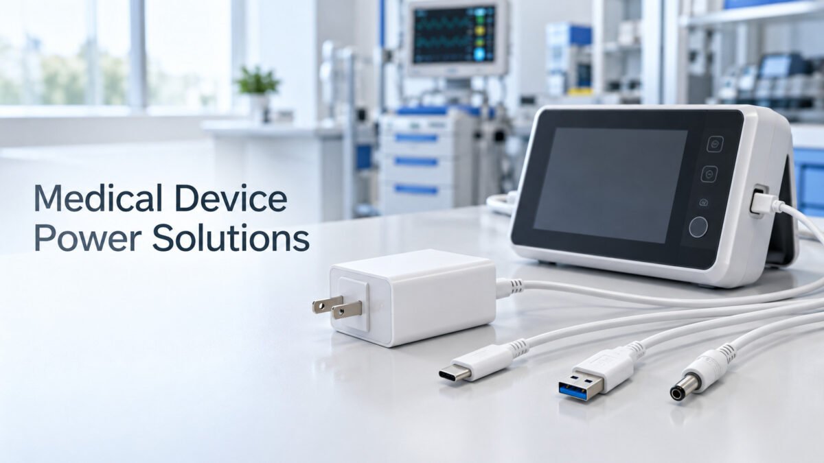
For devices powered through a USB connector, do not select the adapter by connector shape alone. Standard USB power starts at 5 V, while compatible USB Power Delivery devices may negotiate higher voltage and power levels. A USB-C connector does not by itself confirm support for USB PD or a specific charging profile. Verify the device's required charging protocol, supported voltage profiles, maximum power, and cable requirements before selecting a USB power adapter. Fixed-output DC adapters and USB PD chargers should be treated as separate product categories.
1.2 Output Matching
The adapter's nominal output voltage should match the device's required input voltage unless the device manufacturer specifies an acceptable input range. Output accuracy, line regulation, load regulation, ripple, and transient response vary by adapter model and should be checked in the datasheet. Confirm that the adapter's specified minimum and maximum output remain within the device's permitted input range under the expected load and operating conditions.
Do not raise voltage to compensate for some other shortfall. If a device specifies 5 V, an adapter rated above that can over-stress input circuitry even when it appears to fit the same socket. Verify the requirement for each individual device rather than assuming a common figure across a product family. When the device's permitted input range is unclear, do not finalize the adapter until the requirement has been confirmed from the device datasheet or manufacturer.
2. Current Selection
Current, expressed in amperes (A), indicates the maximum output current the adapter is designed to supply under its rated operating conditions. Power is expressed in watts (W) and, for a DC output, is calculated as voltage multiplied by current. After matching the output voltage, select an adapter whose rated current and power meet the device's maximum operating requirements.
2.1 Load Requirement
Total the current drawn by the device during full operation. Product labels, manuals, and datasheets state current consumption in milliamperes (mA) or amperes (A). An adapter's output current should not sit below the device's stated figure, because below that figure the adapter is being asked to supply more than it was sized to deliver.
Where a device powers additional loads — USB hubs, LED lighting, motorized mechanisms, or several downstream peripherals — add the current of every connected load together. The sum of all loads represents the minimum the adapter must be able to deliver, not the primary device alone. Counting only the main unit while ignoring attached peripherals is a common cause of under-specified adapters. Where a load is momentary rather than continuous — a motor spin-up, a heater element switch-on — include its peak figure in the calculation rather than its average.
2.2 Power Margin
Select an adapter whose continuous output rating is at least equal to the device's maximum continuous load. For many applications, a design margin of approximately 20–30% is a useful starting point, subject to the device manufacturer's requirements and the adapter's derating data. For example, a 1 A continuous load may call for an adapter rated at approximately 1.25 A or higher. Motors, heaters, capacitive loads, and other equipment with high startup or transient demand must also be checked against the adapter's peak-current capability, overload behavior, and transient response.
A higher current rating does not normally force extra current into a compatible constant-voltage device; the load draws the current it requires. However, excessive oversizing may increase cost and physical size without improving system performance. Final selection should consider continuous load, peak demand, ambient temperature, ventilation, cable voltage drop, and the adapter manufacturer's derating specifications.
3. Connector Selection
Voltage and current define electrical compatibility; the connector defines physical compatibility. The adapter couples to the device through a DC plug and cable, so both the plug and the wire must suit the device's jack, its polarity, and the layout of the installation. A correct voltage and current are of little use if the plug does not fit or if the polarity is reversed.
3.1 DC Plug Size
DC connectors are produced in a set of standard barrel sizes, commonly identified by the outer diameter and inner diameter in millimeters, such as 5.5 mm × 2.1 mm o 5.5 mm × 2.5 mm. These two figures look similar but are not interchangeable; a mismatch in the inner bore can produce an intermittent connection or no connection at all. In addition to outer and inner diameter, confirm the plug length, contact design, insertion depth, and dimensional tolerances where specified by the device manufacturer.
Measure the device's socket rather than relying on a photograph or a recollection, and confirm both diameters. Where the required plug is uncommon, an adapter can be fitted with an alternative plug size, or a cable carrying the matching connector supplied as required. Listing the plug's outer and inner diameters together is the clearest way to specify a barrel connector, and it removes the ambiguity that comes from naming a connector by visual appearance alone.

3.2 Polarity
Polarity indicates which contact is positive and which is negative. Many barrel-connector adapters use center-positive polarity, but this is not universal. Always match the polarity symbol on the device or its technical documentation. Do not rely on connector size or common market practice, because two adapters with the same plug dimensions may use opposite polarity, and reversing polarity can damage the device's input circuit.
If the label is missing, verify the polarity against the device's service documentation before use. Where polarity genuinely cannot be confirmed, do not power the device on an assumption; resolve the marking first rather than treating the adapter as safe by default.
3.3 Cable Length and Conductor Size
The output cable must carry the required current without excessive voltage drop or temperature rise. Cable resistance increases with length and decreases with larger conductor size, so longer cables or higher-current loads may require heavier conductors. Specify the cable length, conductor size, insulation material, flexibility, and operating temperature according to the application.
Voltage should also be verified at the device input under maximum load, especially for low-voltage systems and long cable runs. If a proposed cable includes USB connectors, protocol-triggering electronics, or voltage-conversion circuitry, it should be treated as a separate engineered cable assembly rather than as a standard passive DC cable.
4. Application Solutions
Across industries, the method described above is applied to three recurring scenarios. The same logic — define the device requirement, size the current margin, then confirm the connector — applies whether the unit is a spare, a custom-ordered item, or part of installed machinery. Working through the checklist in the same order each time keeps the selection consistent and repeatable.
4.1 Replacement Adapter
For a replacement adapter, read the requirements from the original unit's label. Match the nominal output voltage and output type, select an equal or higher current rating, and confirm the connector dimensions and polarity. Also verify that the replacement is regulated where the original device requires a regulated supply. If the original connector is not held in stock, an adapter with an interchangeable DC plug or a companion cable with the matching connector can be supplied instead.
For international markets, confirm the AC input-voltage and frequency range, wall-plug configuration, power-cord requirements, and applicable safety and EMC approvals for the destination market. Certification names should be confirmed against the specific model and its approvals rather than claimed in general terms. Sourcing the adapter and cable assembly under one approved specification can simplify compatibility review, sampling, and quality control.
4.2 OEM Adapter
In an OEM project, the adapter specification should be derived from the device's approved input requirements. The project team defines the nominal output voltage, current and power rating, allowable ripple, connector dimensions, polarity, cable length, and applicable operating conditions. These requirements should be confirmed during engineering review and sample validation before mass production.
OEM projects commonly involve a custom connector type, a barrel length matched to the housing, printed labels, and country-specific plug heads, produced to the customer's drawings and to the certification requirements that apply to the destination market. Because the full configuration is defined up front, the adapter can be delivered as a finished part of the device rather than a generic accessory, and changes made during sampling can be confirmed before a production run begins.
4.3 Industrial Equipment
Industrial applications may require continuous operation, higher ambient-temperature capability, controlled voltage drop over long cable runs, and improved resistance to vibration, dust, moisture, or repeated handling. Selection should therefore consider the adapter's derating curve, operating-temperature range, protection functions, installation method, connector retention, cable construction, and applicable safety or EMC requirements — not only its nominal voltage and current.
Environmental or ingress-protection claims should be specified only for models designed and tested for those conditions. For equipment with USB and DC power connections, list each interface separately and confirm its connector type, electrical function, protocol requirements, and cable length.
Request an OEM Power Adapter Solution
To receive a suitable adapter recommendation or quotation, please provide the device input voltage, maximum continuous and peak current, DC connector dimensions, polarity, cable length, destination market, operating environment, expected order quantity, and any labeling, packaging, testing, or certification requirements.
Depending on project requirements, this can include:
- Custom output cable and DC connector
- Cable length and conductor customization
- Private labeling and packaging
- Country-specific AC plug options
- Sample validation
- Market-specific certification options for selected models