

USB-C Pinout Explained: All 24 Pins, Functions & Wiring Guide
USB-C Pinout Explained: All 24 Pins, Functions & Wiring Guide
USB-C has become one of the most widely used connector types in modern electronic devices. Its reversible design, compact size, and ability to support power delivery and high-speed data transmission make it suitable for smartphones, laptops, tablets, monitors, and many other applications.
However, behind its simple appearance is a relatively complex 24-contact connector arrangement. Each contact has a specific function, including power delivery, grounding, data transmission, configuration detection, and auxiliary signaling.
Understanding the USB-C pinout is important when selecting cables, developing electronic products, designing custom wiring configurations, or evaluating USB-C cable specifications.
This guide explains the USB-C connector structure, the functions of its 24 pins, male and female connector differences, cable wiring principles, and the differences between USB 2.0 and USB 3.x connections.
1. USB-C Connector Overview
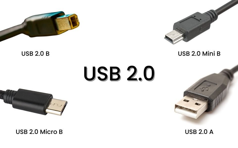
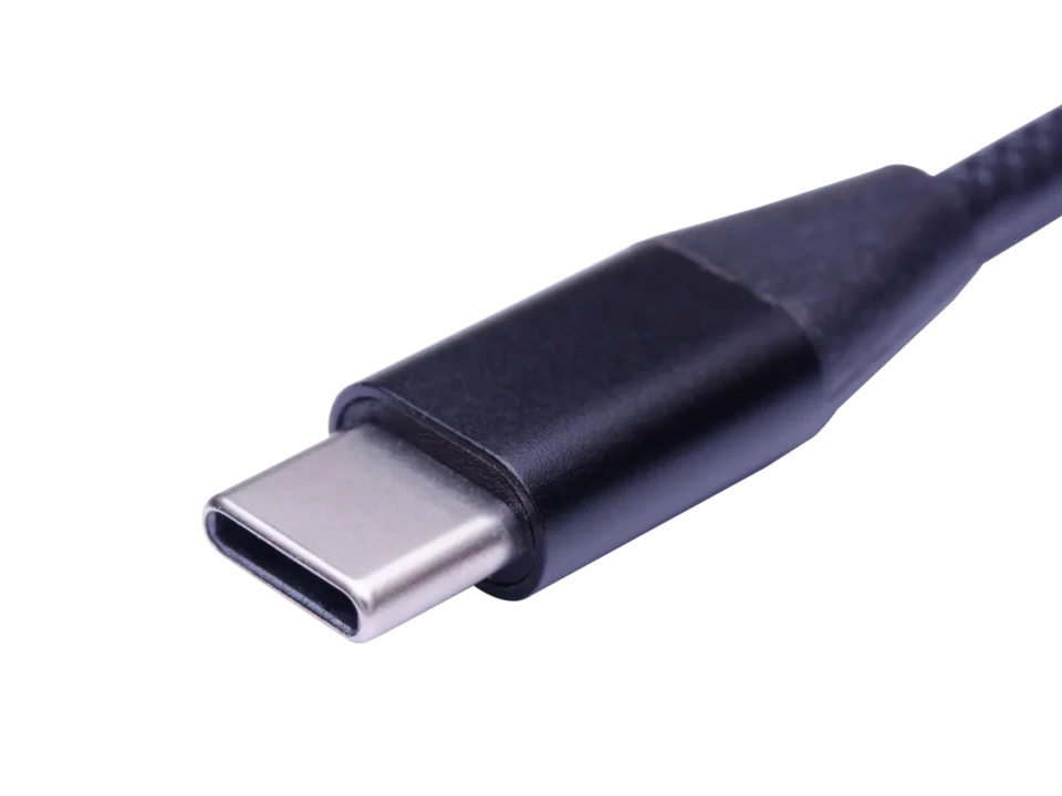
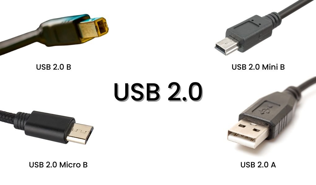
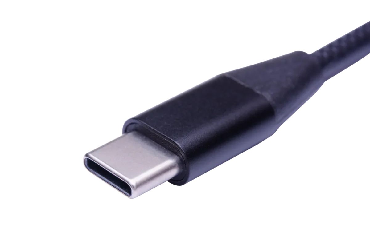
USB-C, also known as USB Type-C, is a reversible connector system designed for modern power and data connections.
Unlike older USB connectors that require a specific insertion orientation, USB-C plugs can be inserted in either direction. This is made possible by the symmetrical arrangement of contacts inside the connector.
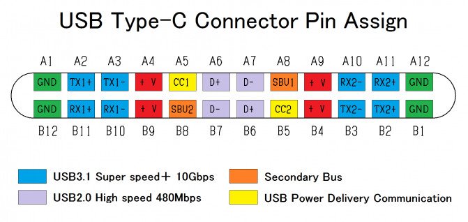
A standard USB-C receptacle contains 24 contacts arranged in two rows, identified as A1–A12 and B1–B12.
These contacts support several functions:
- Power delivery through VBUS.
- Ground connections through GND.
- USB 2.0 data transmission through D+ and D-.
- High-speed data transmission through TX and RX differential pairs.
- Configuration and power negotiation through CC pins.
- Auxiliary signaling through SBU pins.
USB-C Is More Than a Connector Shape
USB-C describes the physical connector, not the complete performance capability of a cable or device.
Depending on the implementation, a USB-C connection may support:
- USB 2.0 data transmission.
- USB 3.x high-speed data transmission.
- USB4.
- USB Power Delivery (USB PD).
- DisplayPort Alternate Mode.
- Thunderbolt on compatible equipment.
Not every USB-C port or cable supports all these functions.
For example, a USB-C cable may support 60W charging and USB 2.0 data transmission without supporting high-speed data or video output.
When selecting a USB-C cable, power capability, data performance, and additional functions should be specified separately.
2. What Is a USB-C Pinout?
A USB-C pinout is the arrangement and functional assignment of the electrical contacts inside a USB Type-C connector.
Each contact is assigned a specific signal or power function. The arrangement allows a single connector to support different communication protocols and power configurations.
USB-C Connector Structure
A standard USB-C receptacle has:
- 24 physical contacts.
- Two rows of 12 contacts.
- A reversible connection design.
- Multiple power and ground contacts.
- USB 2.0 and high-speed data signal contacts.
- Configuration and auxiliary signal contacts.
The two contact rows are identified as:
- A1 to A12.
- B1 to B12.
These pin identifiers are used in technical drawings, connector datasheets, PCB designs, and cable wiring specifications.
USB-C Male and Female Connectors
USB-C connectors are generally divided into two physical forms.
USB-C Male Plug
The male plug is commonly found at the end of a USB-C cable or adapter. It is inserted into the USB-C port of a device.
USB-C Female Receptacle
The female receptacle, also called a socket or port, is commonly installed on smartphones, laptops, chargers, hubs, and other electronic equipment.
The pin arrangement must be interpreted according to the connector type and viewing direction. A plug drawing and a receptacle drawing may appear reversed even though their electrical functions are designed to connect correctly.
3. USB-C Male vs. Female Pinout Differences

Although USB-C male and female connectors share the same general contact system, their physical arrangements and electrical implementations are not identical.
USB-C Receptacle
The receptacle contains 24 contacts arranged in two rows.
It provides duplicated contact positions to support reversible plug insertion.
For example:
- CC1 and CC2 help detect plug orientation.
- The duplicated D+ and D- positions support USB 2.0 operation regardless of plug orientation.
- Multiple VBUS and GND contacts provide power and return paths.
- TX and RX pairs support high-speed data transmission.
USB-C Plug
A standard USB-C plug has a different contact implementation.
For a standard USB-C cable, one CC contact is used for configuration communication, while the other contact position is used for VCONN when required.
The standard USB-C plug also does not implement both duplicated USB 2.0 D+/D- contact positions in the same way as the receptacle.
This is why the plug and receptacle pin diagrams should always be checked separately.
Why Is the Difference Important?
Understanding male and female pin arrangements is particularly important during:
- USB-C connector selection.
- PCB footprint design.
- Cable assembly development.
- Custom connector wiring.
- Electrical testing.
- Connector troubleshooting.
Using the wrong pinout reference can result in incorrect wiring, connection failures, or damaged components.
4. USB Type-C Connector Pin Functions
The 24 contacts inside a USB-C receptacle are divided into several functional groups.
Understanding these groups makes it easier to identify the purpose of each pin.
Complete USB-C 24-Pin Pinout Table
The following table shows the standard USB-C receptacle contact assignments.
| A-Side Pin | Signal | B-Side Pin | Signal |
|---|---|---|---|
| A1 | GND | B12 | GND |
| A2 | TX1+ | B11 | RX1+ |
| A3 | TX1- | B10 | RX1- |
| A4 | VBUS | B9 | VBUS |
| A5 | CC1 | B8 | SBU2 |
| A6 | D+ | B7 | D- |
| A7 | D- | B6 | D+ |
| A8 | SBU1 | B5 | CC2 |
| A9 | VBUS | B4 | VBUS |
| A10 | RX2- | B3 | TX2- |
| A11 | RX2+ | B2 | TX2+ |
| A12 | GND | B1 | GND |
This table describes the receptacle contact assignments. It should not be interpreted as a direct wire-to-wire connection diagram for a USB-C cable. Plug contact assignments and cable wiring must be checked against the applicable connector and cable specifications.
4.1 VBUS and GND: Power and Ground Pins
VBUS and GND are responsible for carrying electrical power through the USB-C connection.
VBUS
VBUS is the main power supply connection.
A standard USB-C connection begins with 5V power. With compatible equipment and successful USB Power Delivery negotiation, the voltage can increase to supported levels.
USB PD 3.1 Extended Power Range (EPR) supports voltage levels up to 48V under the appropriate operating conditions.
GND
GND provides the electrical ground and return path.
The USB-C receptacle has four VBUS contacts and four GND contacts. Multiple contacts help distribute electrical current and provide power and return paths.
4.2 D+ and D-: USB 2.0 Data Pins
D+ and D- form the differential data pair used by USB 2.0.
These signals support data communication at speeds of up to 480 Mbps.
The USB-C receptacle contains duplicated D+ and D- contact positions to accommodate reversible plug insertion.
However, a standard USB-C cable generally uses one USB 2.0 differential data pair rather than two independent USB 2.0 data channels.
4.3 TX and RX: High-Speed Data Pins
TX and RX refer to transmit and receive differential signal pairs.
These contacts support high-speed data communication in compatible USB 3.x and other supported operating modes.
The USB-C receptacle includes two TX pairs and two RX pairs:
- TX1+ and TX1-.
- TX2+ and TX2-.
- RX1+ and RX1-.
- RX2+ and RX2-.
These signal paths allow compatible connections to support higher data rates than USB 2.0.
Because USB-C is reversible, the active signal paths may need to be reconfigured according to the plug orientation.
4.4 CC1 and CC2: Configuration Channel Pins
CC stands for Configuration Channel.
CC1 and CC2 are important for detecting and managing USB-C connections.
Their main functions include:
- Detecting cable attachment and removal.
- Determining plug orientation.
- Identifying source and sink roles.
- Advertising available current through USB Type-C signaling.
- Supporting USB Power Delivery communication.
- Supporting Alternate Mode configuration.
The CC connection is also important for determining how the system should configure its signal paths.
4.5 VCONN: Power for Cable Electronics
VCONN provides power to electronic components inside certain USB-C cables and accessories.
For example, some active cables and electronically marked cables contain internal circuitry that requires power.
VCONN is supplied through the applicable CC contact position that is not being used for the active configuration channel.
This allows the connected system to power cable electronics when required.
4.6 SBU1 and SBU2: Sideband Use Pins
SBU stands for Sideband Use.
SBU1 and SBU2 are auxiliary signal contacts used by supported Alternate Modes.
They can carry additional signals required by compatible interfaces, such as certain DisplayPort Alternate Mode configurations.
These pins are not used for ordinary USB 2.0 data transmission.
5. How Are the Pins of a USB-C Cable Connected?
USB-C cable wiring depends on the cable's intended data performance, power rating, and supported functions.
A USB-C cable designed only for basic charging and USB 2.0 data transmission has a different internal construction from a full-featured cable supporting high-speed data transmission and advanced operating modes.
5.1 USB-C to USB-C Cable Connections
A USB-C to USB-C cable connects corresponding electrical functions between its two plugs, but high-speed signal wiring requires more careful consideration.
Common connection groups include:
- VBUS power conductors.
- GND conductors.
- USB 2.0 D+ and D- conductors.
- CC-related configuration connections.
- High-speed TX and RX differential pairs in full-featured cables.
- SBU conductors where required.
For full-featured cables, the TX and RX differential pairs are arranged according to the applicable USB Type-C cable wiring specification. Transmit and receive paths are connected appropriately between the two ends rather than simply matching every pin number.
The exact contact mapping depends on the plug design, cable assembly type, and viewing orientation used in the connector drawing.
5.2 What Happens When a USB-C Plug Is Reversed?
USB-C supports reversible insertion, so the connected system must determine the orientation of the plug.
The CC pins help identify the orientation and allow the system to configure the appropriate signal paths.
For high-speed data transmission, the system may use a multiplexer to route the appropriate TX and RX differential pairs.
This ensures that the connection can operate correctly even when the plug is inserted in the opposite orientation.
5.3 Full-Featured USB-C Cable Wiring
Full-featured USB-C cables include additional conductors and signal paths to support higher-speed data transmission.
Depending on the supported USB specification, their internal construction may include:
- USB 2.0 D+ and D- conductors.
- SuperSpeed TX and RX differential pairs.
- VBUS power conductors.
- Ground conductors.
- CC and VCONN-related connections.
- SBU conductors.
- Shielding and drain structures.
The exact conductor arrangement depends on the cable category and applicable specification.
A USB-C connector alone does not guarantee that all these conductors are present.

6. USB 2.0 vs. USB 3.x USB-C Cable Pinouts
USB-C cables can support different data transmission standards.
Although they may use the same external connector, their internal wiring and performance can vary considerably.
USB 2.0 USB-C Cable
USB 2.0 USB-C cables use the D+ and D- differential data pair.
Common characteristics include:
- Maximum signaling data rate of 480 Mbps.
- Simpler internal data wiring.
- Suitable for basic data transfer and charging applications.
- No SuperSpeed TX/RX differential pairs required.
These cables are commonly used for smartphone charging and everyday data connections.
USB 3.x USB-C Cable
USB 3.x USB-C cables include additional high-speed differential pairs for SuperSpeed communication.
Depending on the supported USB generation, they can provide higher data transmission rates.
Examples include:
| USB Standard | Maximum Signaling Data Rate |
|---|---|
| USB 2.0 | 480 Mbps |
| USB 3.2 Gen 1 | 5 Gbps |
| USB 3.2 Gen 2 | 10 Gbps |
| USB 3.2 Gen 2x2 | 20 Gbps |
Actual transfer performance depends on the host, device, cable construction, and supported operating mode.
Key Differences
| Feature | USB 2.0 USB-C Cable | USB 3.x USB-C Cable |
|---|---|---|
| Main Data Pins | D+ and D- | D+ and D- plus SuperSpeed pairs |
| Internal Construction | Simpler | More complex |
| Data Speed | Up to 480 Mbps | 5–20 Gbps, depending on standard |
| High-Speed Differential Pairs | Not required | Required for supported SuperSpeed modes |
| Typical Applications | Charging and basic data transfer | External SSDs, docking stations, and high-speed peripherals |
USB 3.2 Gen 2x2 uses two SuperSpeed lanes. It is important not to describe all USB 3.x connections as having the same number of active high-speed lanes.
It is also important to remember that charging power and data speed are separate specifications.
A USB-C cable can support high charging power while providing only USB 2.0 data transmission.
Likewise, a high-speed USB-C cable does not automatically support every charging power level.
7. Why Do 24-Pin USB-C Connectors Not Always Use 24 Wires?
A USB-C receptacle has 24 physical contacts, but this does not mean every USB-C cable needs 24 separate internal conductors.
The actual number of conductors depends on the cable's intended functions.
For example, a USB-C cable designed for charging and USB 2.0 data transfer does not need all the high-speed TX and RX signal pairs used in a full-featured cable.
Common USB-C Cable Construction Differences
Charging-Focused USB-C Cable
A charging-focused cable may include power and ground conductors, configuration-related connections, and the USB 2.0 data pair if data transfer is supported.
USB 2.0 USB-C Cable
A USB 2.0 cable uses the basic data pair and the required power and configuration connections.
Full-Featured USB-C Cable
A full-featured cable requires additional high-speed signal conductors and shielding to support its specified data capabilities.
Depending on the design, it may also include electronic components such as an E-Marker.
What Is the Role of an E-Marker?
An E-Marker is an electronic identification component used in applicable USB-C cable assemblies.
It communicates information about the cable's capabilities to connected devices.
For example, a compliant 5A USB-C cable requires an appropriate E-Marker to identify its supported current capability.
For higher-power EPR applications, the cable must also be specifically designed and rated for the required operating conditions.
An E-Marker does not automatically make a cable support USB4, video output, or a particular data speed. These capabilities depend on the complete cable design.
For more information, see What Is an E-Marker Chip?.
8. How Are the Core Wires Soldered to a USB-C Connector?
USB-C connector assembly requires accurate electrical connections because the contacts are small and closely spaced.
The wiring process depends on the connector structure, cable design, and manufacturing requirements.
Not every USB-C connector uses the same termination method. Some cable assemblies use internal PCBs, while others use different contact termination structures.
Common USB-C Cable Assembly Steps
1. Cable Preparation
The outer jacket is stripped to expose the internal conductors and shielding structures.
Each conductor is prepared according to the required assembly specifications.
2. Conductor Identification
The internal wires are identified according to their electrical functions.
These may include:
- Power conductors.
- Ground conductors.
- USB 2.0 data wires.
- High-speed differential pairs.
- Configuration-related wires.
- Auxiliary signal conductors.
Correct identification is important because different USB-C cable designs use different internal wiring arrangements.
3. Connector Preparation
The connector's internal PCB or contact structure is prepared for conductor attachment.
Depending on the connector design, the process may use soldering, crimping, or other specified termination methods.
4. Wire Termination
The conductors are connected to their corresponding contacts according to the approved wiring diagram.
High-speed signal pairs require particular attention to signal integrity, conductor routing, and shielding.
5. Inspection and Electrical Testing
After assembly, the cable should undergo appropriate inspections and electrical tests.
These may include:
- Continuity testing.
- Short-circuit testing.
- Open-circuit testing.
- Resistance testing.
- Power capability verification.
- Data transmission testing.
- Signal integrity testing for applicable high-speed designs.
6. Overmolding and Final Assembly
After the electrical connections pass the required checks, the connector may proceed to insulation, overmolding, and final assembly.
The finished cable should be evaluated against its approved product specifications.
9. Common USB-C Manufacturing Terminology
When developing or sourcing custom USB-C cables, understanding common manufacturing terminology helps buyers communicate technical requirements more accurately.
Surface Mount Technology (SMT)
SMT is a manufacturing process used to mount electronic components directly onto the surface of a printed circuit board.
It is commonly used in electronic assemblies, including certain USB-C connector designs.
Reflow Soldering
Reflow soldering uses controlled heating to melt solder paste and establish electrical and mechanical connections between components and PCB pads.
It is widely used in SMT production.
Wave Soldering
Wave soldering is a process in which a PCB passes over a controlled wave of molten solder.
It is commonly used for suitable through-hole component assemblies.
Quality Control (QC)
Quality control involves inspection and testing procedures used to verify that products meet their defined specifications.
For USB-C cables, this may include electrical continuity, resistance, appearance, connector assembly, and functional testing.
Alternate Mode
Alternate Mode allows compatible USB-C connections to carry signals from other interfaces.
For example, DisplayPort Alternate Mode enables compatible USB-C connections to transmit video signals.
However, both connected devices and the cable must support the required implementation.
Thermal Management
Thermal management refers to the methods used to control heat generated during electrical operation.
It is particularly important for high-power USB-C cables and connectors, where conductor resistance, contact quality, and operating current can influence temperature.
RoHS Compliance
RoHS refers to restrictions on certain hazardous substances in electrical and electronic equipment.
Applicable material and component requirements should be checked when developing products for regulated markets.
10. Conclusion: Understanding USB-C Pinouts for Better Cable Design
The USB-C connector combines power, data, configuration, and auxiliary signal functions within a compact 24-contact receptacle.
Understanding the pinout is essential when selecting connectors, developing cable assemblies, troubleshooting connections, or defining custom USB-C cable specifications.
However, the number of physical contacts does not determine the complete performance of a USB-C cable.
Power rating, data speed, video support, internal wiring, and E-Marker configuration must all be considered separately.
For product developers and buyers, choosing the correct connector arrangement and cable construction helps ensure that the final product meets its intended electrical and functional requirements.